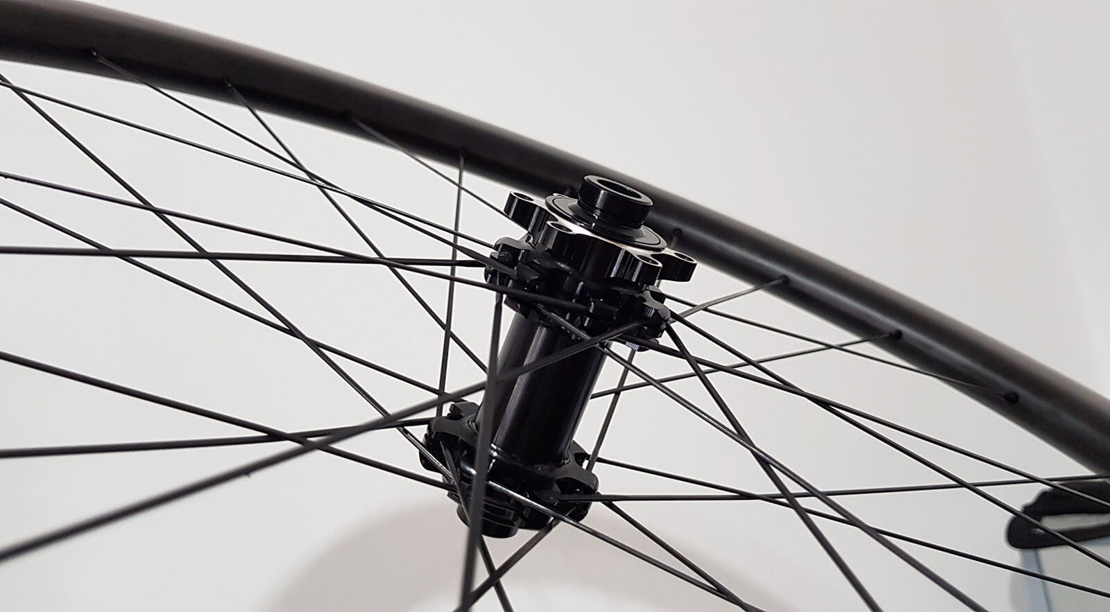
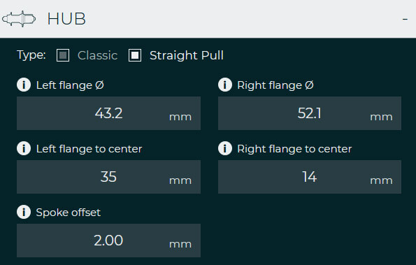
Let’s first look what we are dealing with when you open a straight pull hub calculator, compared to classic hubs measurements. Just like working with classic hubs, we need left and right flange diameter (PCD) and flanges to center dimensions. That is not new, however, taking measurements for these inputs is a little different process.
What, actually, is very different with straight pull hubs is that there isn’t any spoke hole diameter needed whatsoever. The fact that the spoke isn’t classic J-bend shape, instead it is completely straight (hence straight pull), changes the calculation of a spoke calculator for the correct spoke length and different hub measurement is needed. Rather than that there is a variable, called spoke offset.

Measuring left and right flange to center
Just like working with classic hubs, I measure straight pull hubs from the outside in. I start with getting the O.L.D measurement, the parameter that stands for Over locknut dimension or total width of the hub.
On road, disc brakes hubs, 142mm is a number you are most likely looking for.

Using my digital height gauge, I next measure left and right flange to locknut dimension. Just like on two images below, you are looking for a centre of the flange to the locknuts dimension. In our case, measurements for left and right side were 36.00 and 57.00 millimetres. These two values we can use to calculate flange to flange (F.T.F.) dimension and left/right flange to centre variable.
Note: flanges of straight pull hubs are typically wider since spokes are grouped in pairs. When measuring flange to centre or flange to locknut, take the middle of the flange as the reference, even though one spoke is on the outside and one in on the inside of a flange’s centreline.

The thing is that if we subtract 36.00 mm and 52.00 mm from 142 mm (O.L.D.), we get 49 mm, correct? Just a reminder, that dimension is conveniently called Flange to flange distance (F.T.F.). Check the image below to make sure it is so in fact. If a hub has the same diameter at both flanges (PCD), you could just use a digital calliper gauge and get this dimension quickly. But it becomes hard to take accurate hub measurements if one PCD is let say 10mm greater than other. See the problem? That is why I always get flange to locknut dimensions first.

Getting a flange diameter (PCD)
Flange diameter or pitch circle diameter is another variable, we must get for a spoke calculator to work out the correct spoke length for straight pull hubs. I googled for the Powerway’s M42 hub dimensions and found out that it was 51.1 mm for the right and 43,2 mm for the left side. Take a look at the next image and see how a very normal straight pull hub can’t just let you use a calliper gauge to measure flange diameter.

Figuring out the next best “measure-it-yourself” alternative for a flange diameter, I came up with the sum of two measurements. Actually, you are able to measure the inner circle (hub body) diameter and add the rest of the distance (flange) to the spoke bed. Just make sure that the latter measurement is for a spoke bed as this is very important. In my case I get 44.91 mm and 2* 3.1 mm, and this sums up to 51.1 mm. Just about right, considering online cheat sheets said the right PCD is supposed to be 51.1 mm for this particular straight pull hub.


Spoke offset of a straight pull hub
Remember, compared to a classic hub type, a straight pull hub calculator doesn’t need a spoke hole diameter as spokes are not regular J-bend shaped. Rather than that, we are dealing with a spoke offset measurement. And not only that this measurement is a bit hard to take, you will rarely get this dimension of a hub online. So, what is a spoke offset?

Spoke offset, marked as Y in the drawing above, can be defined as the distance from the centerline of paired spokes in the hub's flange to the spoke bed. This is however different with straight pull hubs with radial lacing pattern where this parameter becomes needless.
Note: If your straight pull hub shape dictates a radial lacing (0 cross), just enter a 0 in a spoke offset.
So how do you tackle measuring a spoke offset? I usually first measure the thickness of a flange where spokes are mounted, just like in the image below. In my example I came up with 7.0 – 7.1 mm. The centerline should be at 3.5 mm right? Now, at least as I see it, there are two ways of measuring our straight pull hub's spoke offset.

The first way... Take a look how my spoke's head is dead flat with my calliper gauge in the image above. And since the centerline is 3.50mm from the edge of the flange consider next method. If we now subtract spoke head thickness, which is 1.50mm (image below) in my case, from 3.50 mm, we get 2.00 mm. This means that the spoke bed starts 2.00 mm from the centerline of our hub's flange.
Important: The koeficient of this parameter's effect on the final spoke length in straight pull spoke calculator is 1. Meaning, if you get this measurement wrong by a full millimetre, your final spoke calculation will also deviate by 1.00 mm.

This was one method, as my spoke head came completely flat to the outside of a flange. But what happens if spoke bed is hidden inside, and so the spoke head dead flat with the outside, just like in the image below?
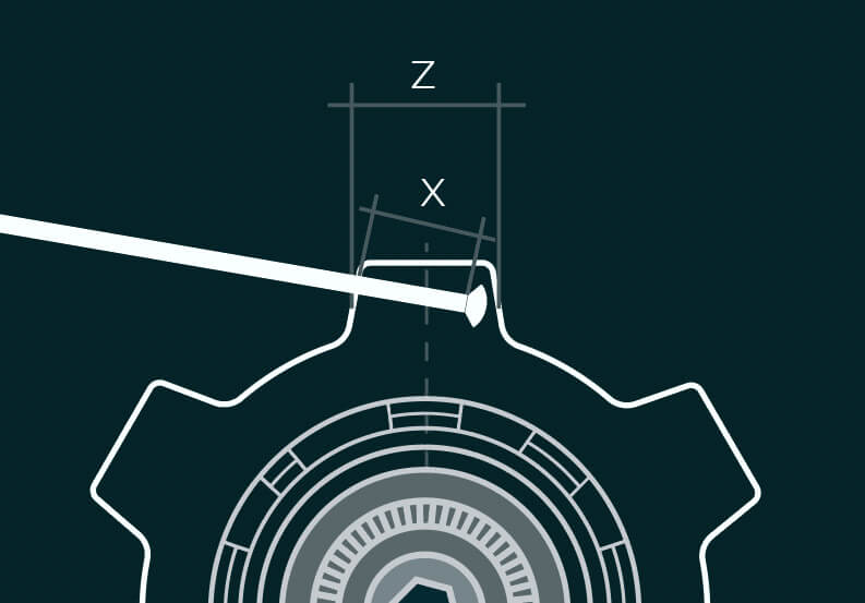
In this case I would also at first take the flange's thickness measurement, marked with Z variable. But then, just use one reference straight pull spoke to take the X value. You could do that by having one sample straight pull spoke cut to a specific length, let’s say 50mm. If you insert this reference straight pull spoke into the spoke bed and take readings of the visible part (the remaining length of the spoke), you should calculate the distance of the spoke inside the flange. From this measurement you then just need to subtract our predefined centreline to get the spoke offset.
Straight pull hub measurements
I was using my free Hub measurements visual tool to get a clear picture of my hub's dimensions. Just write down your hub's measurements as you go and this tool will also help you with calculations. In the end you will also be able to export your data to SpokeCalc.


References
Measurements for wheelbuilding - Taking your own measurements with confidenceDefault lacing pattern
Unlike the classic hub type, intended for J-bend spokes, the geometry of straight pull hubs allows only one, the default lacing pattern. Spoke holes are drilled at a specific angle through the flange ears and as such, the default lacing pattern cannot be altered in any way. Failing to recognise or ignore the intended lacing pattern and you will come up with a faulty spoke calculation.
Usually, a lacing pattern (crossings) increases with spoke count, and so as a rule of thumb most straight pull hubs with 24 spoke holes have 2-cross lacing pattern as a default and most straight pull hubs with 28/32 spoke holes are meant to be built using the 3-cross lacing pattern. However, sooner or later, exceptions happen, so the lacing pattern cannot be predicted or lightly generalized across different hub manufacturers, as even they rarely write that information on their pages.

Therefore, to be absolutely sure, what is the default lacing pattern for a straight pull hub, simply put some spokes inside the spoke holes on each flange at a time and allow them to auto align to the hole’s angle. You will soon be very sure whether it is a 2-cross or a 3-cross lacing pattern intended for a hub you are using.

Inside the App Spokecalc, while saving a hub, you can easily store also the default lacing information that will come handy for future use.
Enjoyed this article?
Buy me a coffee to support my work!
Every coffee helps fuel more content like this!
Final thoughts
Working with straight pull hubs can confuse a novice wheel builder, of course. But once you figure out how straight pull spoke calculator works and what measurements are actually needed, it all becomes clearer. It takes a bit more time, no doubt, but even without having factory dimension sheet of a straight pull hub, by reading this article, you should be competent enough to start wheel building with straight pull hubs on your own.
Just be as accurate as you can be. Take precise measurements of your straight pull hub and you shall get the correct spoke length. I will cover up what happens if you get one dimension wrong and how wrong separate measurements can affect the final spoke calculation in one of my next articles. Happy wheel building!
About author

Aljaž Trenta
Author and founder"As a cycling enthusiast, bike mechanic and self-taught web designer, combining several of my passions and skills to build SpokeCalc was a great fun for me."