
To rewind a bit and illustrate the background, the email’s title said it all — “New Headache.” Here’s the original message, trimmed to the essentials:
“A few days ago, I purchased an old Shimano dynamo hub, model HB-NX70. What intrigued me was that it had only 24 holes. With an ERD of 596 and a 2X cross, I calculated spoke lengths of 280 and 281 mm—close enough that I almost used just one length but decided to stick with both.
I began lacing the wheel, starting with the disc brake side so that the spokes pulling on the rim when braking would be coming out of the hub. As I tightened the nipples until the spoke threads disappeared, I felt something was off. Some spokes were loose, others overly tight, and I couldn’t even make it all the way around the wheel before I had to stop and inspect.
On one side of the wheel, all spokes coming out of the hub were loose, while the others were tight; on the other side, it was the reverse. What’s wrong here? I took everything apart, checked each component, and then… surprise. As you can see in the attached photo, the hub flanges had no spoke offset—each hole directly opposite its counterpart.”
Ok, before we proceed, let's address also the basic wheelbuilding data for the project:
- Effective rim diameter (ERD): 597 mm
- Pitch circle diameter (PCD) L/R: 80/80 mm
- Left flange to center: 23.2 mm
- Right flange to center: 28.9 mm
- Spoke hole diameter: 2.5 mm
With the strange basis of this case, you can probably imagine it will be a multi-step spoke length calculation, with a fracture lacing pattern included as a jewel on top of it all.
Note: In case you find a more intuitive solution to the problem - "Bless you!" - and please kindly oversee my overstating the bizarreness of this particular wheel project.
STARTING WITH FAMILIAR PATTERN
Even with a solid understanding of spoke calculator magic, I find that drawing things out often brings clarity to the situation. And this was exactly the case I resorted to yet again.
Below, you’ll see the initial project stage, where I intentionally exaggerated one hub flange size to highlight the alignment issue — no offset between spoke holes on either flange. In a typical 24-hole hub, one side would have holes offset by 15 degrees in relation to the other flange, but here they’re perfectly aligned. A detail so minor to oversee until somewhere along the lacing stage only to then encounter severe issues.

With spoke holes directly opposite each other, I started on the disc brake side, opting for a familiar 2-cross lacing pattern. As noted in the drawing, the layout of this 24H wheel means that the two spokes that cross each other nearest to the flange are 90 degrees apart where they enter the rim.

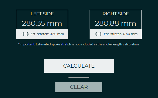
The first step of calculating spoke length confirmed calculation results from the first email nicely - 280.4 mm for the left side while the right-side calculation was ignored. At this point, however, note the 90 degree angle between adjacent spokes in such a configuration.
Great, with that out of the way, it is time to move on to the tricky side of the wheel.
CREATIVE SOLUTION FOR THE OTHER SIDE
Moving on to the right side of the wheel in Stage 2a, I dropped the opacity of the previously added spokes for clarity. Still viewing from the same side, thanks to the enlarged left flange, I added two spokes and crossed them once. However, due to rim constraints, the angle between these spokes wasn’t the 90 degrees I had on the left side but was reduced to 60 degrees.

Since backside spokes between flanges of the hub are aligned at hub flanges, we are dealing with a slightly smaller angle between adjacent spokes, thus different lacing pattern. In other words, we are not quite on a 2-cross but still dealing with larger than 1-cross lacing pattern (see note below).
Note: For context, in this setup, with the spokes’ rim entry points, two adjacent spokes on the flange would be 30 degrees—or two rim holes—apart in a standard 1-cross pattern.
What we ended up with here was more of a 1.5-cross lacing pattern, which brings us back to the topic of fractional lacing patterns. I explored this in-depth in a popular article: 2:1 Two-to-one lacing pattern - Calculating spoke length for a 2:1 spoke lacing pattern.
Note, however, that opting for such a lacing pattern will bring an inevitable compromise to the table.

Repeating this pattern would not be possible by simply copying the pairing 60 degrees around the flange. Focus closely on the drawing above, to keep this pattern alive, we would have to leave out one hole in the flange in the process.
So, what shows the spoke calculation?
Going for a 1.5 cross-lacing pattern inside the spoke calculator results in 8 pcs of 272 mm long spokes.


LAST SPOKES ROW
With all the groundwork laid, we’re now down to the last row of spokes. This row, unpaired with any others on the left flange, presented its own challenges.
For visual clarity, I erased the front row of disc brake side spokes from Stage 1. This last row of spokes, positioned in the right flange, could very well be “trailing” spokes, as the drawing suggests—but finding the correct spoke length is where it gets interesting.

To simplify, we again need to focus on spoke angle like in the previous case. If lacing radially, a spoke hole would be aligned directly with a rim hole. At 1 cross lacing pattern, the angle between two adjacent spokes at the rim is 2 * 15 degrees or 15 degrees from the center point (if you imagine a radial spoke in the middle). Continuing the logic, the same reference angle in 2 cross setup would be 45 degree (or 90 degrees between spokes as shown in the Stage 1b drawing). Here we are at 30 degrees, basically at half point between 1- and 2- cross. We land at 1.5 cross.
Those four spokes should be turned at an angle facing the rim that is the same as the angle for the adjacent spoke that was inserted step before this, when we made 4 spoke pairs with 1.5 cross. Those two spokes are one hole apart looking at the flange or two holes apart looking the rim; the angle remains the same.
Since we’re once again dealing with a 1.5-cross lacing pattern, we can re-use the second spoke length calculation — 4 pcs at 272 mm.
PUTTING IT ALL TOGETHER
To sum up, this three-step spoke length calculation case yielded all the necessary spoke lengths for the project.
On the left side (disc brake side), we’re using 12 spokes in a 2-cross lacing pattern, each with a length of 280.4 mm. On the right side, we have four spoke pairs (8 pcs) arranged in a 1.5-cross fractional lacing pattern, where the calculated length indicates we should use 272 mm spokes. The remaining four spokes calculated lastly are again laced with 1.5-cross fractional lacing pattern and the length remains, 272 mm.


And client's words after receiving the post-build email?
"I built the wheel strictly following your instructions and everything went well. All spoke tips ended similarly flush with nipple heads, indicating the spoke length calculation was absolutely correct."
FINAL THOUGHTS
Hopefully this case study provides valuable insights into working with an uncommon hub design. By examining the alignment of spoke holes and exploring various lacing patterns, I am definitely not sure whether this is the right or the only way to go. But then again I've been able to clarify some complexities that arise in wheel building.
Navigating the 2-cross and 1.5-cross setups emphasized the need for precise spoke length calculations and demonstrated how unique challenges can lead to different solutions. Using visualization and methodical analysis, we can address even the more unconventional aspects of wheel building.
That said, until next time, enjoy wheel building!
Enjoyed this article?
Buy me a coffee to support my work!
Every coffee helps fuel more content like this!
About author

Aljaž Trenta
Author and founder"As a cycling enthusiast, bike mechanic and self-taught web designer, combining several of my passions and skills to build SpokeCalc was a great fun for me."