A sub-1000 g wheelset - A practical guide for first-timers in building with carbon fibre spokes -
Published: March 6, 2026
Last edited: March 6, 2026
Author: Aljaž Trenta
Carbon spokes have gone completely mainstream over the last few years, no doubt about it. And yet it happened so quickly that many traditional wheel builders feel left out, or at least hesitant to enter this new territory. Some are cautious because of the material itself. Understandably, as carbon fibre behaves differently, which, naturally, induces fear. Others simply prefer to stay away from ultra-light builds, often associated with fragility or short service life. To put this into practice, I built a 998 g wheelset using lightweight components from Light Bicycle.
Note: The project started with ultra-light carbon fibre components, supplied by Light Bicycle. Of course, carbon spokes were involved. It was actually the company’s desire to make an explainer article with tips & tricks for the first-timers dealing with carbon spokes.
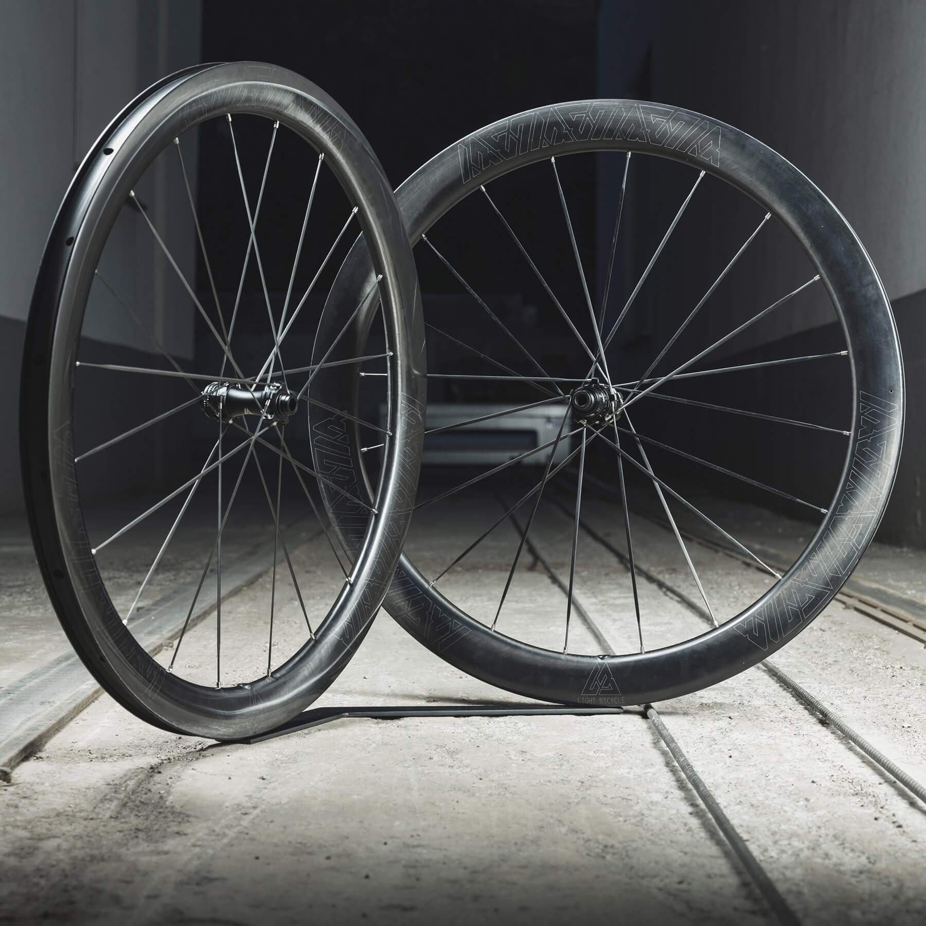
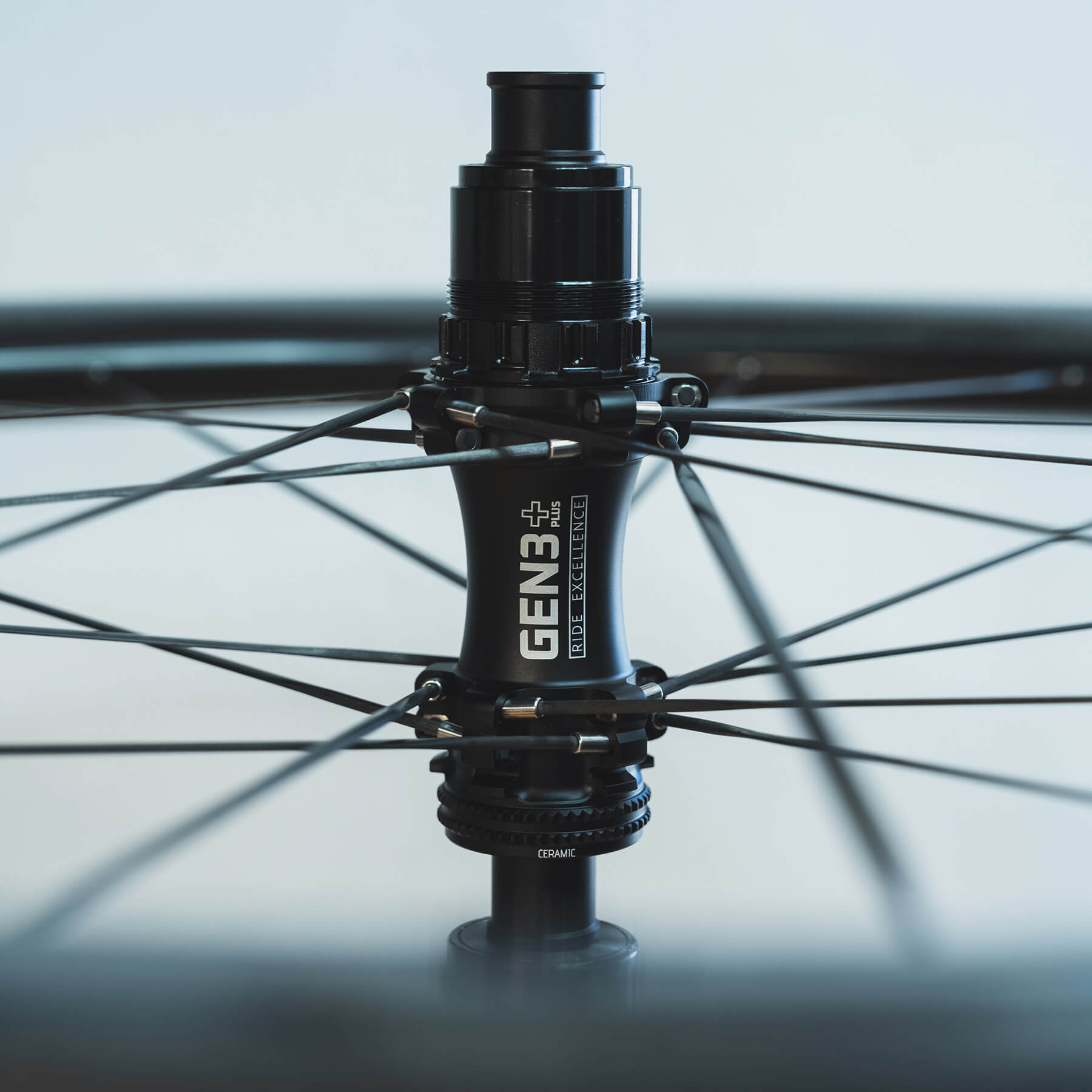
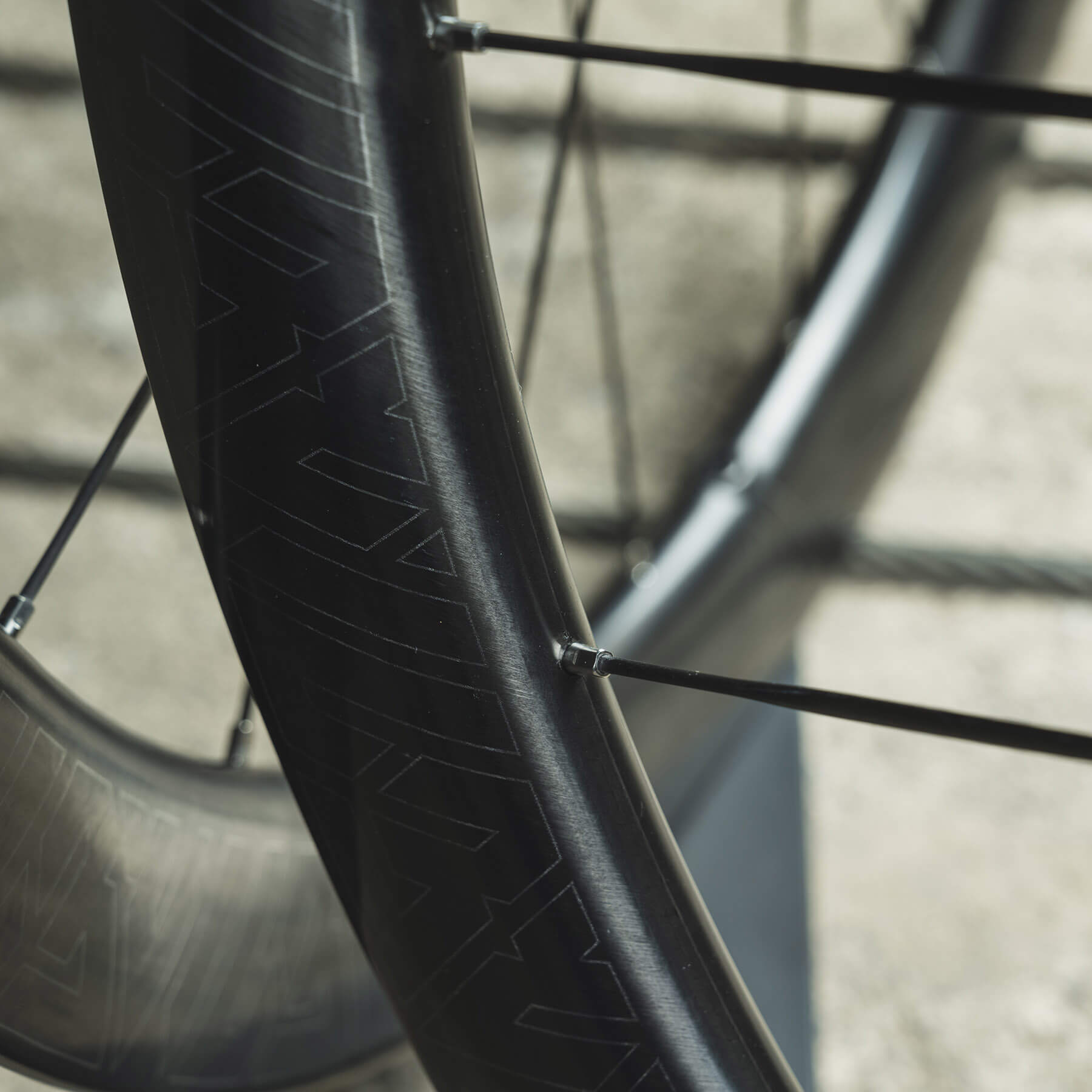
Featherweight carbon build. Tipping the scale at just 998g with 25 mm internal width rims, it just shows impressive engineering in the field of carbon composites use in cycling.
If you’ve never handled carbon spokes before, they feel a bit different. From the moment you hold one in your hand, so light it almost questions basic physics, to the first time you lace and tension a wheel and realise they don’t behave like stainless steel at all.
If it comforts you, I was also hesitant at the beginning as well. It all started similarly to disruptive inventions in every other field. Lots of drama at first, extreme pricing of first products, and lots of incompatible standards being introduced.
Through time, the trend however shifted. It seemed manufacturers gradually, but quietly aligned on at least higher-level standards we now see go full mainstream, allowing better general compatibility and wider serviceability.
Recognizing that momentum and expecting it to continue, this article is not here to boost hype, but to offer real-life practical advice. And along the way, I’ll walk through the small but important adjustments that make carbon spokes predictable. From measuring spoke length correctly, to understanding real elongation under tension, to a simple spoke offset checking method.
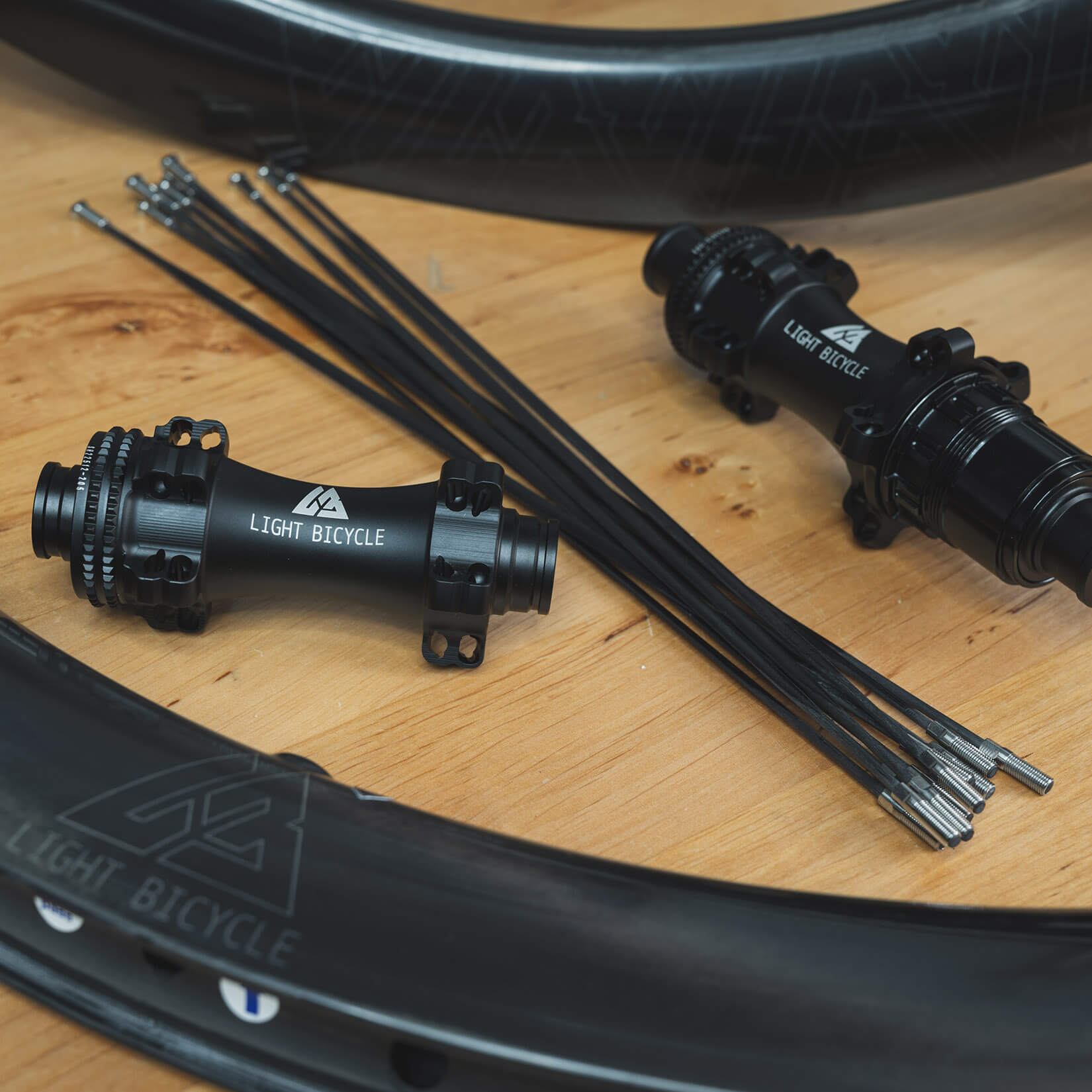
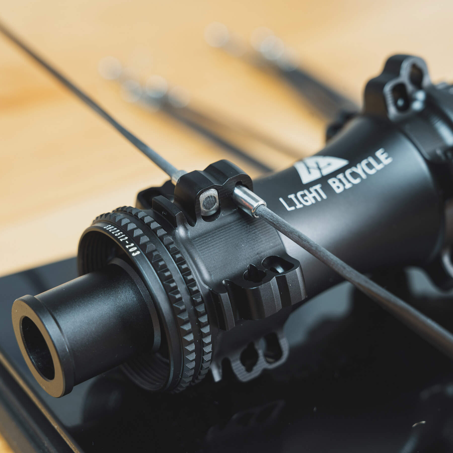
And if you are not familiar with the Light Bicycle, they are one of the most prominent carbon fibre cycling components manufacturers in China. For this particular build, they supplied:
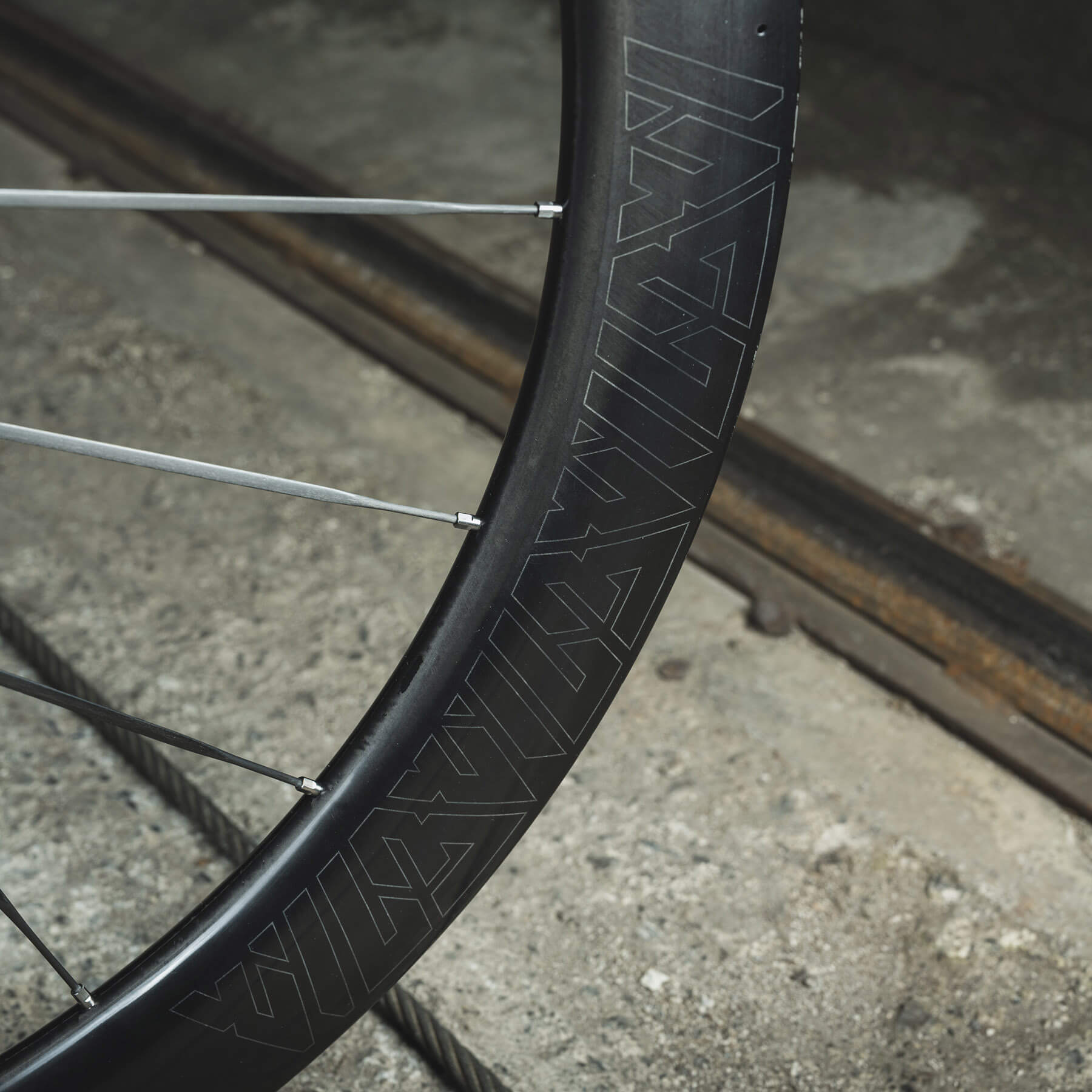
Light Bicycle Airia 47/52mm rims with 25mm internal width
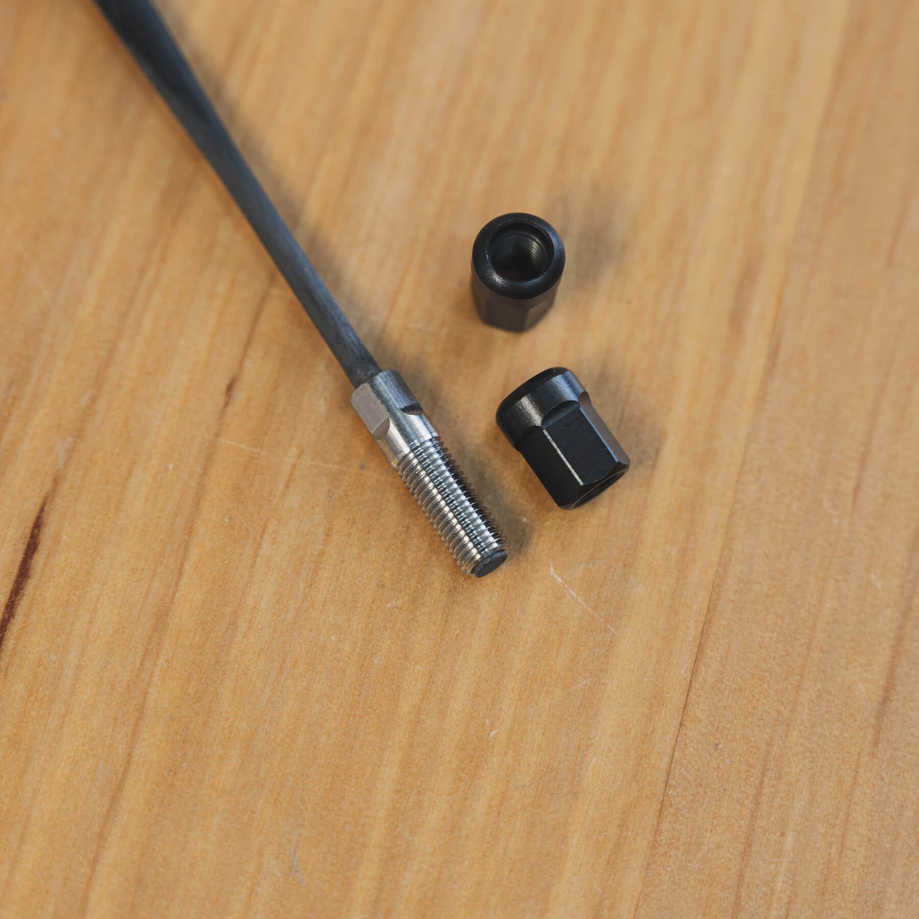
Light Bicycle Thrust-4 Carbon Ti-T-Head (for Gen3) 3.75 x 1.1 mm carbon spokes
Having recently released the all-new Thrust-4 Carbon Ti T-Head (Gen 3) spokes, this build focused on practical tips and handling techniques specific to carbon spokes.
Although carbon spokes entered the market in the mid-1990s, they remained low-volume, high-end niche products for many years. Early designs were often bonded directly to the hub or rim, which meant servicing required specialised carbon fibre expertise. As a result, replacement of damaged spokes was far from straightforward.
I still remember how owners of the Lightweight products sent their wheels to Germany for servicing while receiving a replacement set of wheels in the meantime.
Only in more recent versions did carbon spokes evolve into fully replaceable products with broader serviceability. As nicely outlined by Particle Bike, the industry has by now supposedly reached the fourth generation of carbon spoke development.
Early designs featured bonded metal inserts with threads to fit conventional spoke nipples, but struggled to reach mainstream adoption as builders remained hesitant, in general not trusting the joint between two different materials. While still available, however, those transitional versions only pushed evolution forward.
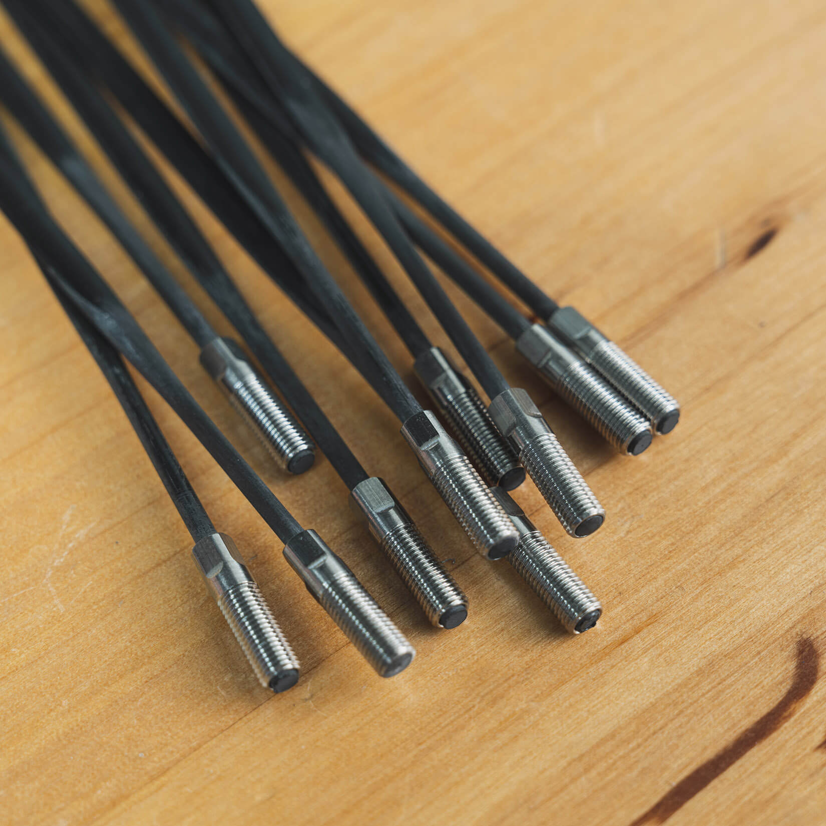
An uniform, oversized M4 thread insert at the end of the spoke has really improved the serviceability of carbon spoked wheelsets.
The most notable recent changes, that sum up the mainstream version of carbon spokes, include:
Oversized metal head inserts, designed to better support the spoke at the hub flange, and excluding inline joint.
T-head or reinforced round head designs, aimed at addressing one of carbon’s main weaknesses, spoke twist.
Uniform oversized thread interfaces with the most common being M4, at the rim end (or even double threaded).
Internal hex drive nipples, allowing simplified installation and adjustments from inside the rim bed.
Compared to the round spoke head, the newer age T-Head metal insert was introduced to shield the spoke from twisting around at the hub which is arguably one of the biggest weaknesses such spokes might have.
The last generation of carbon spokes, using robust metal inserts, M4 type thread inserts, and round or T-head geometries, represents the first truly workshop-friendly carbon spoke systems. They can be built, tensioned, and serviced by any experienced wheel builders without any specialized composite repair knowledge. And that is a fundamental shift that helped carbon spokes gain such a momentum.
Measuring traps
Paying attention to how spoke length is specified
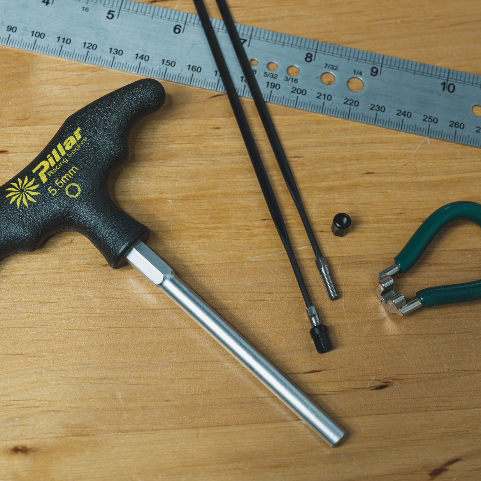
Errors in measuring or during the calculation phase won’t just cost time. They can result in complete rebuilds and expensive spoke replacements. Due to their prices, carbon spokes are not something you want to 'trial & error' through it. Slow down and get it right the first time.
Important: in general, carbon spokes are measured end-to-end, meaning in contrast to regular stainless straight pull spokes, head thickness is included in the specified spoke length.
One critical detail often overlooked is how spoke length is defined.
Most carbon spoke manufacturers specify spoke length as the end-to-end distance: from the beginning of the head to the outermost end of the thread. Meaning the entire spoke length is included in the stated dimension. For builders used to traditional stainless straight-pull spokes, this can be a little confusing at first.
Stainless straight-pull spokes are typically measured only up to the neck, excluding the head thickness. If you apply that traditional assumption when calculating carbon spoke lengths, particularly when determining flange spoke offset, you will likely end up with spokes that are 2–3 mm too short.
And with internal nipples, that margin is unforgiving.
Important note: The recently introduced Sapim CX-Carbon is measured like a conventional straight-pull spoke — up to the neck, excluding the head. To my knowledge, this makes it a lone exception rather than the rule.
For that reason, always verify how a manufacturer defines spoke length before ordering. A simple confirmation avoids costly surprises later on. Also be aware that due to production charachteristics, tolerances for carbon spoke length are set pretty loosely and can stretch towards 0.5 mm differences.
Measuring hub flange spoke offset
Hub specification sheets are not always available. Sooner or later, a wheel builder has to measure hub geometry independently. Among all dimensions, spoke offset in the flange is usually the trickiest. It is small, easy to misread, and difficult to measure precisely even if having high-precision calipers at hand. Yet it impacts the spoke length calculation to a relatively large degree.
A real-life hub measuring experiment made me think of a simple, yet very effective method for measuring spoke offset for carbon spoke-type hubsthat removes most of the uncertainty, shown below.
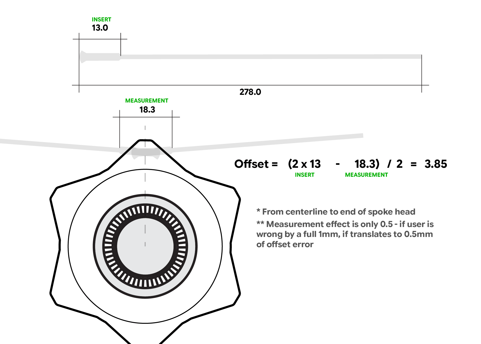
Spoke length always includes the spoke head. So instead of trying to measure flange thickness and guess where the spoke “sits”, we identify the true termination point, the end of the spoke head inside the flange.
Modern stainless or titanium spoke head inserts are manufactured to tight tolerances. For the purpose of this example, let's assume, the insert head length is exactly 13.00 mm. That known dimension becomes our reference.
Simple yet effective hack to measure spoke offset in the flange by measuring distance between the ends of the metal interfaces at the spoke head.
By dry-fitting a spoke pair into opposite flange holes and gently pulling them apart, we measure the distance between the outermost ends of the spoke head inserts. Now follows the simple part.
We deduct 2 × the known insert reference dimension from our measured value and divide the result by two. What remains is the spoke offset from hub centerline to the end of the spoke head. That last detail matters.
This value represents the full offset, including the spoke head, which is actually different from what a traditional straight pull spoke length calculation expects.
For carbon spokes that are sold in lengths excluding the spoke head (for example, Sapim CX-Carbon, as mentioned above), the calculation changes slightly. In that case, we must additionally deduct 2 × the spoke head thickness, because the published spoke length does not include it. A small distinction, but since spoke head thickness usually ranges from 2 mm to 2.3mm, making a mistake here can easily result in a wrong spoke length if overlooked.
When spoke offset is listed in a hub spec sheet
If the previous section covered how to measure spoke offset yourself, let’s now consider the scenario where the manufacturer conveniently lists it in the hub’s technical specifications. That should make things easier, right? Not quite.
Even with a stated spoke offset, misuse is still possible. The critical question now becomes: Does the specified spoke offset include the spoke head thickness or not? A careful builder should pause for a moment here.
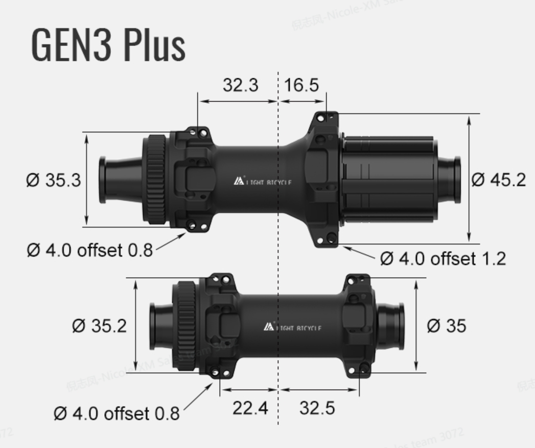
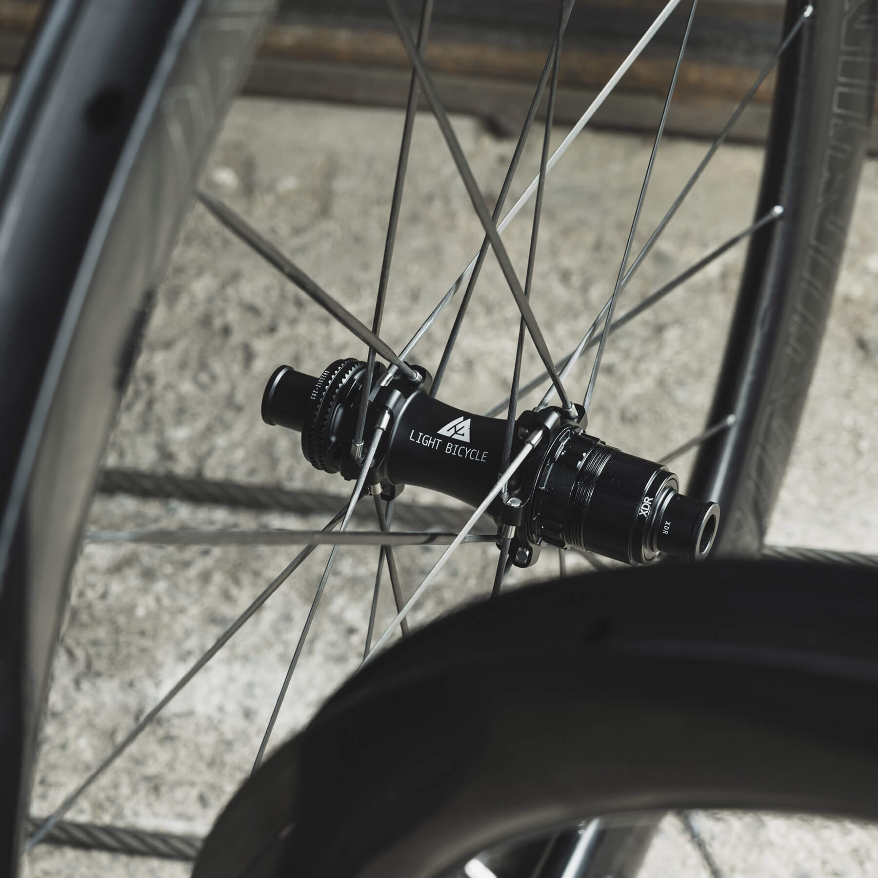
Manufacturer's hub specs for this Gen 3 Plus Speed hubs being used in the build suggest relatively small spoke offset, but does it include spoke head?
In practice, offsets between 0 and 2 mm generally indicate values excluding spoke head thickness. The logic behind this assumption is actually straightforward. If a stated offset of, for example, 1.3 mm already includes head thickness, then the “native” flange offset (without the head) would be negative. Such a configuration is far less common and therefore more an exeption rather then a default interpretation.
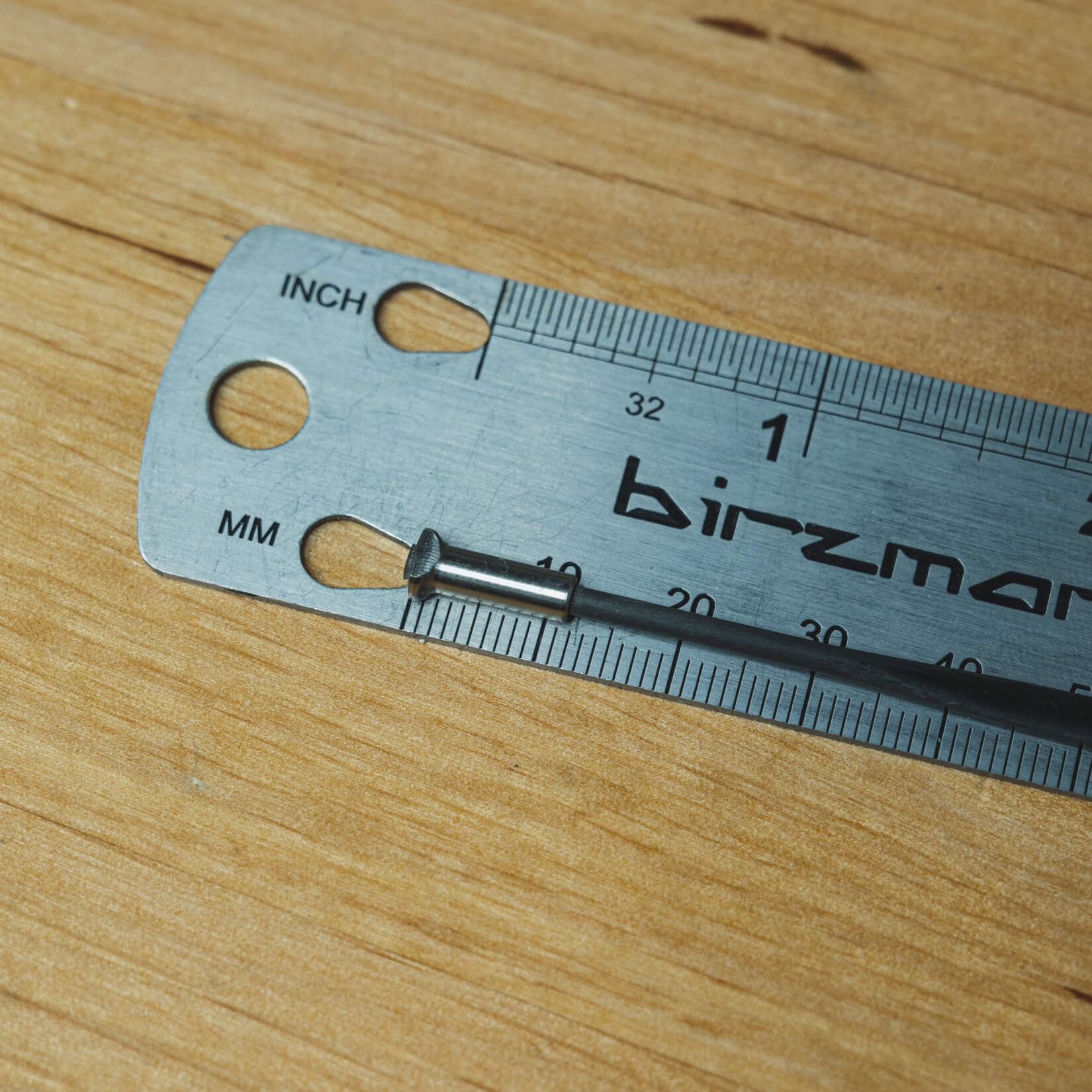
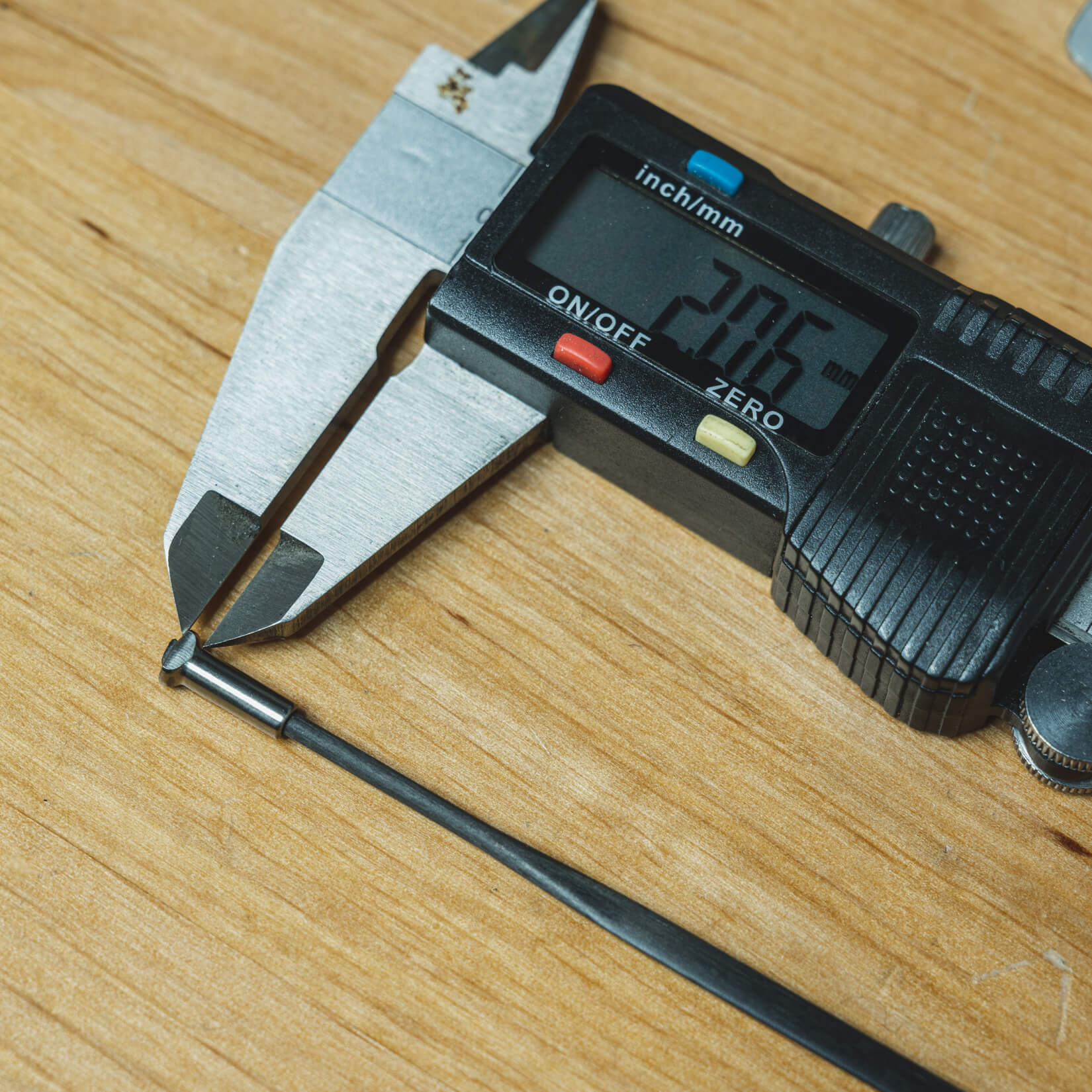
Measuring a T-Head design spoke head thickness which comes at around 2mm for Thrust-4 Carbon Ti-T-Head (for Gen3) carbon spoke.
Note: Head thickness for the typical round and T-Head design is around 2.1 - 2.3mm, in our case a little less as shown on the photo below.
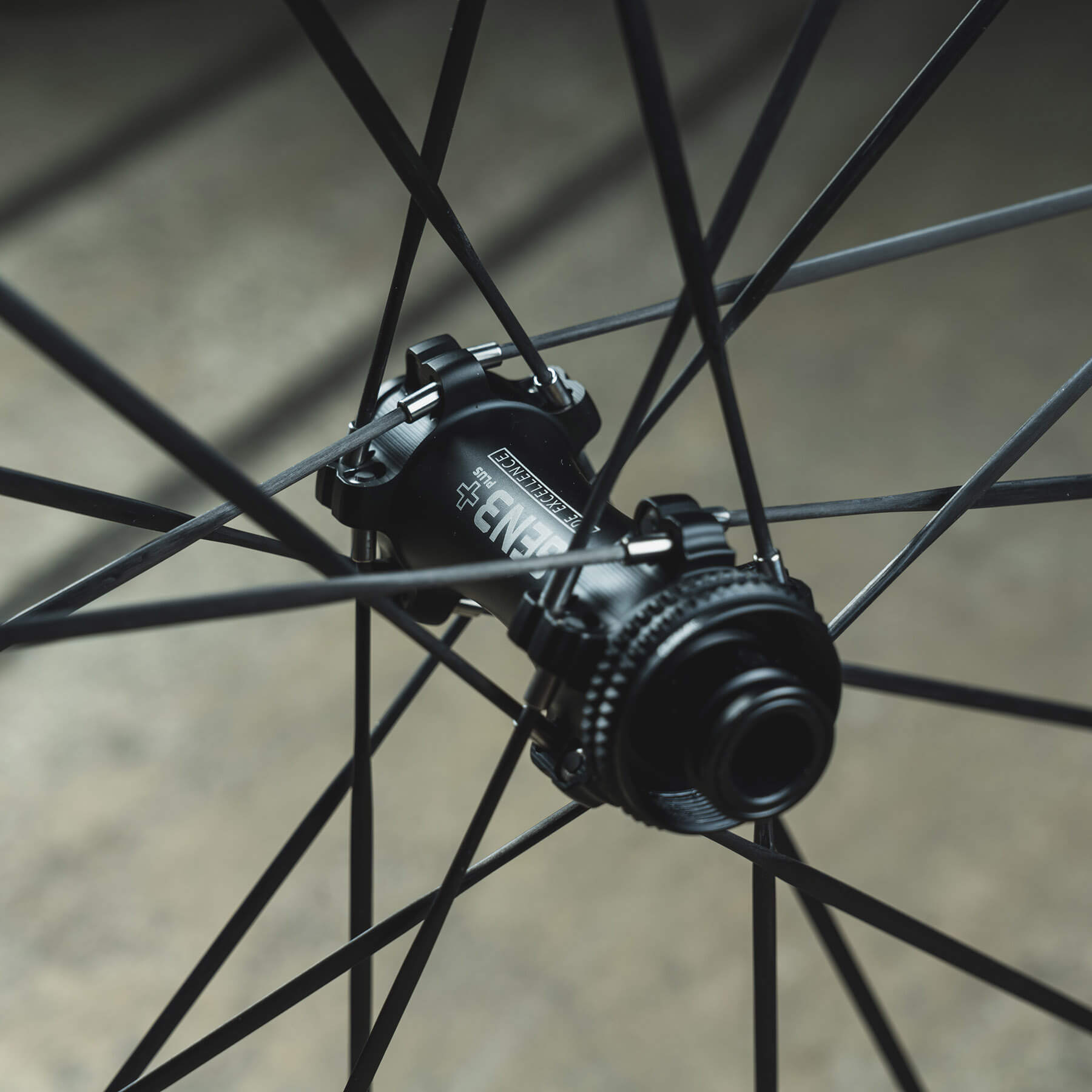
After asking Light Bicycle to supply the technical specifications of the new GEN3 Plus hubs, I encountered exactly the scenario described above. The specified spoke offset for the front hub is listed as only 0.8 mm. This does not mean the measurement is incorrect per se, yet it strongly suggests it must have been taken from a CAD model at the transition from neck to head, while spoke length itself is specified end-to-end. If not careful here, a wheel builder can quickly make a costly error.
A quick glance at a close-up photo of two opposing adjacent spokes immediately reveals we are dealing with a much larger offset, since the spoke heads sit almost a full flange ear thickness apart (approximately 6 mm, measured). Applying the rechecking technique described in the previous section shows that the spoke inserts lie roughly 19 mm end-to-end apart. Given that the spoke head insert length is 12.00 mm, a quick calculation of spoke offset gives (19 mm − 2 × 12 mm) / 2 = 2.5 mm.
Alternatively, if the manufacturer states a 0.8 mm spoke offset while the spoke head thickness itself is 2 mm, then the true offset to the end of the head would be approximately 2.8 mm. That puts our measured result very close and at the same time confirms the method is reliable.
A quick glance at the spokes positioning inside the hub flange suggests we are dealing with much larger effective spoke offset than stated on the manufacturer's specs.
On the other hand, larger values such as 2.55 mm on the non-drive side and 3.80 mm on the drive side in one of my recent builds strongly suggest that the offset already includes the spoke head.
For straight-pull spokes, SpokeCalc outputs spoke length from the thread end at the rim to the stated spoke offset point at the hub. If your spoke is measured and specified as a full-length dimension including spoke head thickness, then the offset you enter into the calculator must also include the spoke head thickness (for example, 3.80 mm in my case).
This is absolutely crucial: the offset specifications and spoke length definition must match for an accurate spoke length calculation. This section alone explains how offset should be treated and why blindly copying manufacturer numbers can be risky.
Spoke positioning inside the rim
Besides hub geometry, the final position of the spoke is ultimately defined inside the rim. Carbon spokes with metal inserts introduce another variable that must be considered.
The drawing below proposes a close-to-ideal positioning of a spoke under tension inside the rim by respecting the metal insert specifications, which are as follows:
Total insert length: 15 mm
Thread length: 9 mm
Diameter: 4 mm
Square spoke key size: 3.35 mm
Proposed spoke positioning inside the rim, where sufficient thread engagement while still having enough exposed surface on the outside to hold it with a spoke key were both taken into consideration.
Similar to standard stainless spokes, we are aiming for sufficient thread engagement to ensure a strong connection between the internal nipple and the spoke. Yet here we encounter a trade-off. As thread engagement increases, the metal insert with the square spoke-key section gradually disappears deeper into the rim wall.
If the spoke is too short, threads of the metal insert remain visible outside the nipple. If the spoke is too long, however, the insert may bottom out in the nipple thread while simultaneously sinking the square spoke-key section inside the rim wall, leaving nothing to hold with a spoke key.
Based on the manufacturer-stated nipple seat diameter (NSD) for the Airia 52 mm model, measured at 534 mm, and knowing exactly where the nipple seat bed begins, we can estimate the real thread engagement. By targeting a sufficient yet defensive 7.5 mm thread engagement, the final spoke position inside the rim still leaves enough exposed surface on the outside to securely hold the carbon spoke with a spoke key during tensioning.
An uniform, oversized M4 thread insert at the end of the spoke has really improved the serviceability of carbon spoked wheelsets.
Note: Ultra-light rims with wall thickness around 2.5 mm make spoke positioning even less forgiving, as spoke length errors become more visible. Having an accurate rim geometry reference such as NSD is actually a brilliant solution to this as it helps fine-tune the ideal spoke position inside the rim.
While spoke positioning inside the rim defines the final thread engagement, hub geometry still determines the geometric spoke length itself. And looking at unusually wide flange ears of modern carbon spoke hubs, this introduces another question.
Do we really need four spoke lengths?
Carbon spokes use oversized stainless steel or titanium head inserts. Those inserts force hub manufacturers to design wider flange ears to allow opposing spokes to sit parallely, similar to standard straight-pull hubs. That detail alone changes something fundamental: the effective flange-to-center dimension.
And once that changes, a logical question appears... Do we actually need four different spoke lengths, one for each spoke row?
Interestingly, I’ve received several questions around this over the past year alone. And at first glance, the answer seems obvious. Each row sits at a different position, so logically each should require a slightly different spoke length.
But how significant are those differences in reality? And are they substantial enough to justify ordering four separate spoke lengths, especially in builds where left and right sides already differ? Let’s look at a real spoke calculation and see what actually happens.
Our reference rear hub has the following flange-to-center dimensions from official tech specs:
Left flange to center: 32.3 mm
Right flange to center: 16.5 mm
Manufacturer's hub specs for this Gen 3 Plus Speed hubs being used in the build suggest relatively small spoke offset, but does it include spoke head?
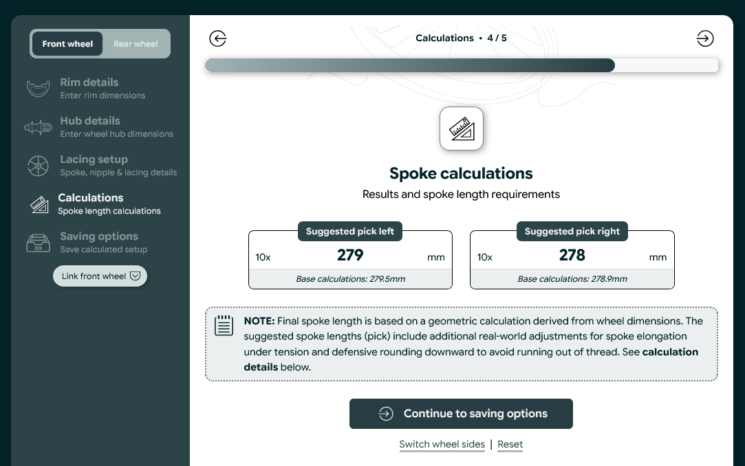
These measurements are accurate alright, however they refer to the middle of the flange ear, not the actual spoke row positions. Using those values results in:
279.5 mm non-drive side
278.9 mm drive side
Initial spoke calculation used to establish the base geometric spoke lengths. See the smaller base calculations in the second row.
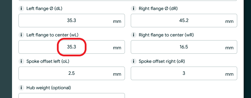
Now comes the catch. Spoke holes on that hub are actually positioned 6 mm center-to-center apart, making the flange ear width at 14 mm. That means each flange has two distinct spoke rows, inner and outer, and each row sits at a different effective flange-to-center distance. Actually a common situtation for carbon spoke hubs. If we adjust our base flange to center measurement to actual row-specific dimensions, this becomes:
35.3 mm for outer non-drive
29.3 mm for inner non-drive
13.5 mm for inner drive
19.5 mm for outer drive
Just by looking at raw data, we can notice moderate changes. Now several recalculations is needed, adjusting only the flange-to-center distance while keeping everything else identical, to get spoke lengths as follow:
279.8 mm (+0.3 mm) → 35.3 mm outer non-drive
279.1 mm (-0.4 mm) → 29.3 mm inner non-drive
278.8 mm (-0.1 mm) → 13.5 mm inner drive
279.1 mm (+0.2 mm) → 19.5 mm outer drive
Initializing sub calculations by only adjusting flange to center dimensions to better suit spoke positioning of each spoke row inside the hub flange.
The result shows 0.7 mm difference on the non-drive side and only 0.3 mm difference on the drive side, respectively. So yes, row positioning does influence spoke length. However the real question is no longer if it matters, but more like:
“Is ±0.7 mm significant enough difference to justify separate spoke lengths?”
And that actually depends on several factors, such as nipple engagement, spoke stretch, and, most importantly, the availability of spoke lengths from the distributor. Having spoke lengths available in every millimetre certainly makes things easier in our case.
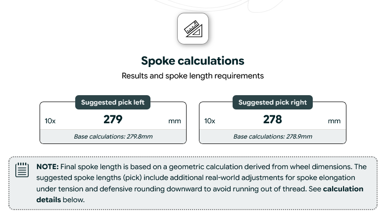
Let’s focus on the outer non-drive side spoke length, which calculated at 279.8 mm, a +0.3 mm difference compared to the original 279.5 mm reference calculation. Now things become interesting.
Focus on the Base calculations row on the left (i.e. 279.8 mm). It shows the updated spoke calculation after the left Flange to center dimension was adjusted to match the outer spoke row.
Suggested spoke lengths already include real-world considerations: expected spoke elongation under tension and a conservative rounding strategy to prevent running out of thread engagement. With those factors applied, SpokeCalc advises selecting 279 mm as the most balanced outcome for both non-drive side rows.
However, if only even spoke lengths are available, the next possible options become either 278 or 280 mm with the latter out of the question since elongation must be also accounted for. At that point, we are no longer debating tenths of a millimetre. Accounting for carbon spoke elongation under full tension (elongation deducted from base result), the effective deviation is more than 1 mm from the ideal, comparing available 278 mm spoke choice and 279 mm spoke length suggestion. That now becomes a question of a practical compromise.
Distinctive spoke rows at the hub flange indicate we are dealing with four different effective spoke lengths.
When spoke lengths are available in 1 mm increments, the decision remains fairly simple. When they are not, the burden shifts back to the wheel builder, who must choose between slightly excessive thread exposure or reduced thread engagement
Note: At the time of writing, SpokeCalc does not output individual spoke lengths for each spoke row on wide flange body hubs. The calculator currently works with a single flange-to-center value per side, as provided by the manufacturer. Having said that, this might very well evolve in the future. Providing row-specific data could improve decision-making, especially inside the Rounding Suggestions moduue, where small variations across rows must be considered to select the most appropriate final spoke length within a practical tolerance range.
Lacing the wheel
Spoke alignment is crucial
Carbon spokes do not forgive rushed handling. To avoid sudden spoke twisting or unnatural side forces, I strongly recommend building on a dedicated lacing jig. Keeping the wheel horizontal allows the spokes to fall naturally into position without forcing them into the flange at awkward angles.
The process itself does not take longer than a traditional stainless spokes build. Especially since spoke count on most modern carbon-spoke wheels is greatly reduced to only 20H or 24H configurations. The most important detail during insertion is blade orientation.
Aligning the spoke blade with the plane of the wheel will ensure smooth sinking in of the spoke head at the hub.
Carbon spokes must remain perfectly aligned with the plane of the wheel from the very beginning. When properly aligned, the spoke head sinks smoothly and naturally into the flange during the first stages of tension build-up. No creaking, forced seating, or sudden tension drops.
Visual references and hacks around it
However, there is a drawback. When working with internal nipples, we lose one very convenient advantage, visual control. With external nipples and stainless steel spokes, it’s easy to pre-position every nipple to the same thread engagement before tensioning. Doing so dramatically shortens the early phase of truing, particularly roundness inspections, because the wheel already starts from a relatively even base.
With internal nipples, however, that control is reduced. We can’t see the threads directly during lacing, and initial positioning becomes less precise. But there are ways around that.
Before beginning tension build-up, I wind all nipples across the wheel to approximately the same visual reference. Usually, leaving one or even two full threads visible from the outside. Although not quite the same, the aim is the same: to provide me with a rough but consistent baseline.
From that point onward, precision comes from counting turns. That alone minimizes the occasions a builder returns to recheck radial trueness in the final stages of tensioning the wheel.
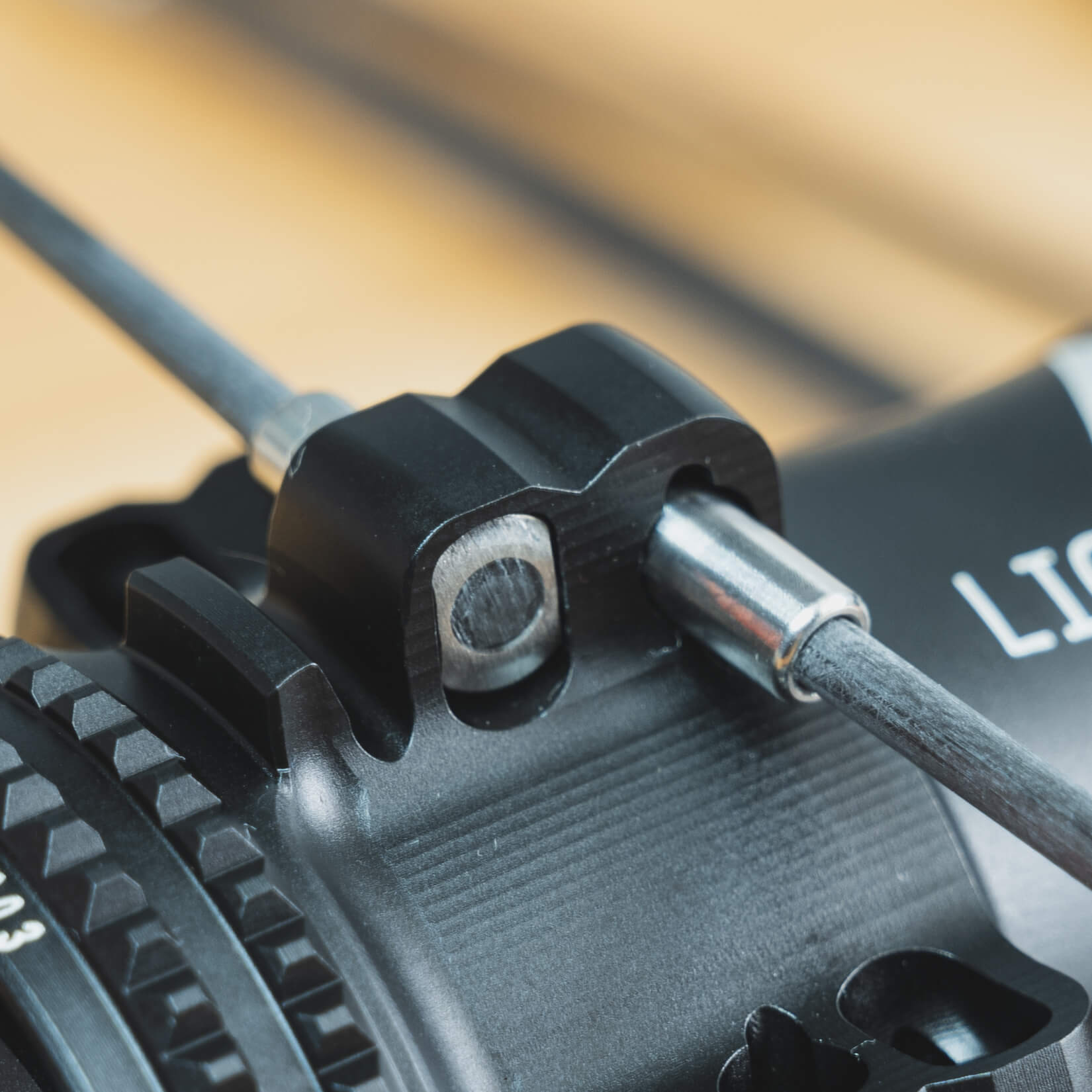
Slowly threading an internal type nipple onto the spoke using a 5.5 mm hex key leacing a thread or two for visual reference later on.
Note: Sinking the spoke and holding it with a key during final tension avoids twist and protects insert bond.
Interlacing should be avoided
Although this should feel intuitive, at least once you understand the material, it is worth emphasizing clearly: no interlacing. Spokes should follow a clean path from hub to rim without being crossed over or under another spoke.
Traditional stainless-steel builds often use interlacing to increase lateral stiffness and reduce spoke movement under load. With carbon spokes, this logic does not apply in the same way.
Modern hubs designed for carbon spokes differ significantly from classic straight-pull stainless hubs. The flange geometry is typically wider, and spoke holes are larger to accommodate inserts or reinforced spoke heads.
Inserting spokes into the hub flange before lacing. Remember, no interlacing on spoke crosses.
It is not uncommon to see hub flange ears exceeding 14 mm in width, with opposing spoke holes positioned 6 mm apart laterally. The spoke lines are already separated by design, which alone justifies “no interlacing” advice.
Introducing interlacing in such a layout (at least where spokes are not glued together) would forces spokes into unnatural bending paths, create contact points under load, and concentrate stress where it is not intended. Just let the spokes run straight.
Tensioning phase
Spoke positioning while building up the tension
Taking into account everything discussed in the previous section already reduces correction time later in the build, especially once tension begins to rise.
From a traditional wheel building standpoint, the transition from lacing to tensioning marks a distinct new phase. At this point, special attention must be paid to how spoke heads sit in their respective flange seats.
During early tensioning, spokes are still fairly loose. They can shift, rotate, or momentarily lift from their seat when the wheel is transferred from the lacing jig to the truing stand.
This can be avoided mainly through increasing tension gradually (slow adjustments) by limiting the number of nipple turns per pass while simultaneously observing spoke heads sinking into their flange seat.
One of the appealing reasons to try building with carbon spokes lies also in the minimum additional tooling needed.
Slow, controlled tensioning allows the spoke head to bed in progressively rather than snapping into place under sudden load. Once tension begins to rise into across the working range, another factor becomes critical, preventing spoke wind-up. Holding the spoke blade with a key while turning the nipple prevents rotation and protects the joint between the metal insert and carbon fibre sole underneath.
Stiffness and elongation
The area of most interest, particularly to first-time builders, is undoubtedly the behaviour of a carbon spoke under tension.
Carbon spokes are generally considered significantly stiffer than equivalent stainless steel spokes, which contributes to a more responsive wheel and better power transfer. And upgrading to a carbon spoke wheelset, this will be the very obvious feel, the rider notices.
However, stiffness is probably better understood through elongation models, which translate real spoke behaviour (i.e., actual stretch) across the tension range where wheels are built in practice.
Recently, I updated my tension meter calibration jig with a digital dial gauge to capture accurate and consistent elongation readings of a spoke within its working tension range. This allows direct measurement of spoke stretch instead of relying purely on theoretical calculations.
There are some takeaways to highlight, though:
Shape matters. Despite different spoke profiles, the behaviour under tension remains broadly similar. Spoke thickness has a greater influence on elongation than blade width, a fact known already from tension charts for conventional steel bladed spokes.
Expect manufacturing tolerances. Carbon spokes currently show wider tolerances than traditional stainless spokes. As a result, tension and elongation readings can vary slightly between spokes. Good practice includes batch testing and regular recalibrations of the tension meter for precise work.
Measurement outweights estimation. Due to the complex properties of carbon fibre composites, elongation is best measured directly rather than estimated purely using Hooke’s law and a standard carbon fibre modulus.
The graph below illustrates elongation curves for several carbon spoke models of similar dimensions across a typical wheelbuilding tension range.
Elongation models
Carbon spoke behaviour when tensiod based on measured elongation data.
Spoke stretchWhen tensioned
Spoke reference
Spoke
Material
Dimensions
Stretch at 120kgF
Carbolite • Alpina Raggi
Carbon
3.10 x 1.00 mm
0.8 mm
Thrust-4 Ti-T-Head • Light Bicycle
Carbon
3.75 x 1.10 mm
0.73 mm
Generic • Other
Carbon
3.80 x 1.15 mm
0.65 mm
RC-1 • Sapim
Carbon
2.20mm
1.22 mm
CX-Carbon • Sapim
Carbon
3.00 x 1.50 mm
0.76 mm
Tension charts
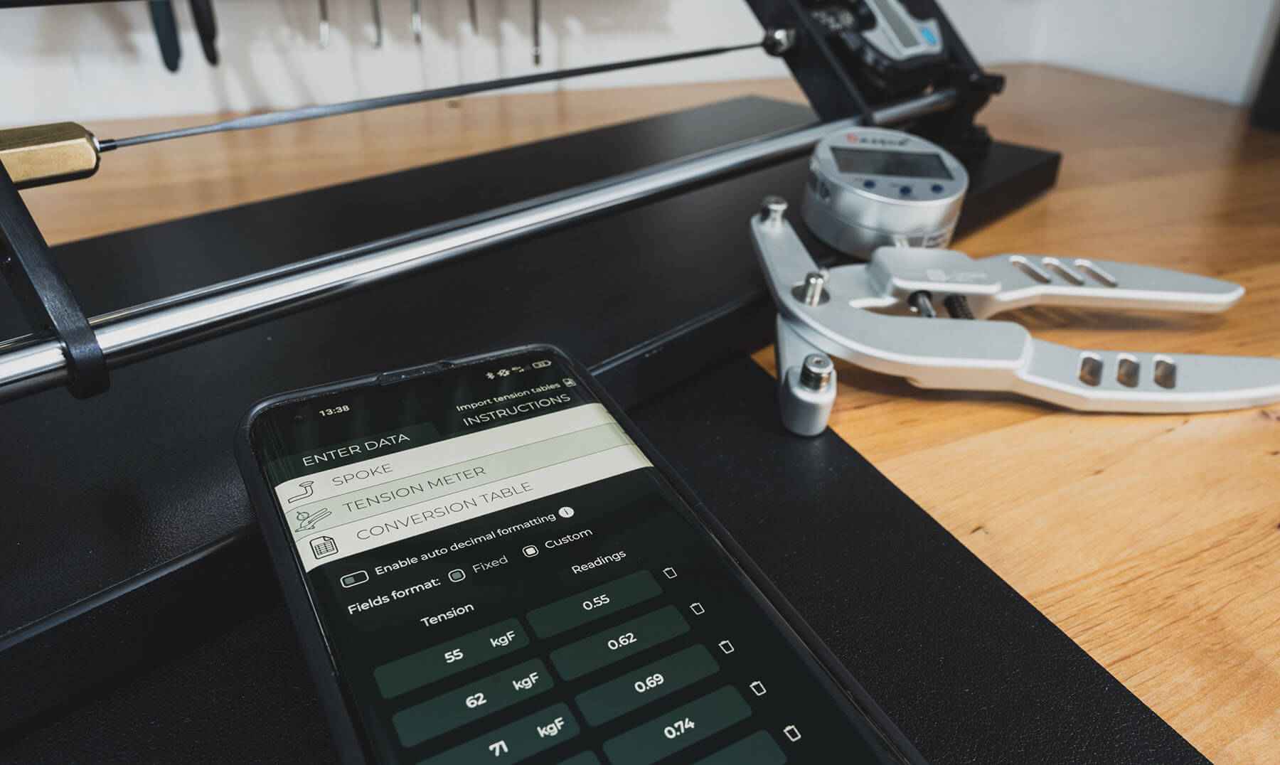
For accurate tension readings when working with lightweight carbon spokes, it is advisable to rely on up-to-date conversion charts and make a periodical refresh of your tool's tension tables a routine.
And this brings us to probably the biggest drawback of carbon spokes. Most tension meter manufacturers still don’t provide calibrated charts for them. As a result, wheel builders often have to create their own conversion charts, either by owning a calibration jig themselves or by having them performed by peers in the wheel-building community.
However, be aware that blade thickness tolerances alone can slightly distort tension readings, so good practice includes checking and recalibrating the meter with each batch of spokes.
Interestingly, the oversized blade of many carbon spokes feature, can actually prove convenient. Blade widths above 3 mm, such as on the Light Bicycle spokes used here (i.e., 3.75mm), make positioning between the tensiometer pins easier and more stable. The wider blade also helps the builder quickly spot unintentional spoke twist or confirm that the spoke sits correctly aligned inside the meter.
Using a Tension chart app to create a custom tension table for carbon spokes.
If the previous section examined stiffness through elongation, there is another perspective that helps explain it, spoke deflection inside the tension meter. Below are two real calibration charts comparing two modern carbon spokes.
At one end, weighing only 1.8 g per spoke, sits Alpina with its new carbon model, the Carbolite. It is a bladed spoke with dimensions of 3.10 × 1.00 mm. Compared to Light Bicycle’s 2.7 g Thrust-4 spoke, measuring 3.75 × 1.10 mm, the differences are notable not only in elongation but also in deflection behaviour.
When tensioned and inserted into the pins of a tension meter, the Alpina spoke shows consistently smaller readings across the working tension range. In practice, this makes it behave similarly to performance based steel spokes such as Ultralite Aero models or Sapim CX-Ray, which many wheel builders are already familiar with.
On the other hand, the Thrust-4 Ti-T-Head spoke produces larger readings at comparable tensions, indicating lower deflection in the tension meter. This again highlights a key point: spoke thickness plays a major role in how a spoke reacts to deflection, often more so than blade width alone.
Spoke
55 kgF
62kgF
71kgF
80kgF
89kgF
98kgF
106kgF
116kgF
124kgF
Thrust-4 Carbon Ti-T-Head • 3.75 x 1.10 mm
0.76
0.82
0.92
0.99
1.08
1.12
1.18
1.23
1.28
Carbolite • 3.10 x 1.00 mm
0.57
0.64
0.70
0.77
0.85
0.90
0.97
1.01
1.04
Measured tension meter deflection of two carbon spokes across the working tension range.
A compromise in weight here (only about 38 g per wheelset ) is almost negligible. It does make me wonder whether chasing the absolute lightest spokes is really worth it if stiffness takes a hit in the process.
That thought came back to me while leaning onto the wheel during stress relief as it held my weight nicely. A reassuring feeling actually, and something worth keeping in the back of your mind.
By now, I am sure you eagerly waiting a photo gallery of the final build. That said, enjoy!
Titani
FINAL THOUGHTS
Carbon spokes for mainstream use are evolving quickly, and this article only reflects current insights and the most common challenges a wheel builder might run into today. As the field progresses, techniques for working with carbon spokes will continue to evolve as well, leaving room to refine both the practice and the knowledge around it.
The fact, however, remains. Carbon spokes are nothing to be worried about when approached systematically. They are simply a little different, and that behaviour can be predicted. Once you understand how they respond under tension and adjust your handling, measuring practices, and tensioning accordingly, they should become a little less intimidating.
Even if you never fully switch to building wheels with carbon spokes, chances are you will eventually meet them in the workshop for servicing.
With the help of components provided by Light Bicycle, this article introduced some practical tips & tricks sourced from real builds, hopefully making carbon spokes feel a little more manageable for the wheel builder who encounters them.
Enjoy wheel building.
About author
Aljaž Trenta
Author and founder "As a cycling enthusiast, bike mechanic and self-taught web designer, combining several of my passions and skills to build SpokeCalc was a great fun for me."
NEWSLETTER
Signup for my newsletter and get notified when I publish new wheelbuilding articles for free!
NEW!!! We've just released a total wheelbuilding tool. Calculate spoke length, save components, calibrate tension meter and use tension app.