
Bonus: Visual build templates
Revisiting two-to-one lacing pattern
Two-to-one (2:1) lacing, also known as triplet lacing, is a relatively modern lacing pattern where one side of the wheel (the dominant side) has twice as many spokes as the other. This design helps balance spoke tension, improving wheel strength and durability. It is particularly beneficial for wheels that experience high torsional forces, such as rear wheels on road and mountain bikes.
The SpokeCalc app now fully supports two-to-one lacing, making it easier than ever to calculate the correct spoke lengths for this pattern. If you're working with a two-to-one lacing setup, I highly recommend familiarizing yourself with the underlying logic behind this spoking method. In the article linked below, I break down the calculations and provide build templates to help you visualize and apply the pattern correctly.
If you are encountering two-to-one lacing pattern, be sure to check out the underlying concept of such a spoking pattern that I have written about in the article 2:1 Two-to-one lacing pattern - Calculating spoke length for a 2:1 spoke lacing pattern.
Note: Two-to-one lacing falls into the category of fractured lacing patterns, meaning the lacing number is not a whole number.
Disclaimer: Ensure Component Compatibility
Before starting your build, make sure your hubs and rims are designed for two-to-one (2:1) lacing. Since this pattern uses different spoke counts on each side, your components must be drilled accordingly.
Check the spoke hole layout on your hubs and rims to confirm compatibility. If your components support 2:1 lacing, you can confidently proceed with your custom build.
The Dominant and Non-Dominant Side
The dominant side refers to the wheel side with twice as many spokes as the other. This setup is typically used where the wheel experiences greater torsional or lateral forces, requiring extra reinforcement.
- On front wheels with asymmetric geometries (e.g., disc brake hubs), the dominant side is the left (non-drive) side.
- On rear wheels, the dominant side is the drive side, where more spokes support the cassette’s load.
The non-dominant side has fewer spokes, but the spoke length calculation remains unchanged. Multiple lacing patterns can be used for this side, and the calculator assumes standard length calculations apply. Since the spoke count imbalance only affects one side, you can treat the non-dominant side like any other wheel build.
In the following sections, where build templates are presented, the focus will be on the dominant side, as it is the key factor in two-to-one lacing.
Enabling Two-To-One Lacing inside App SpokeCalc
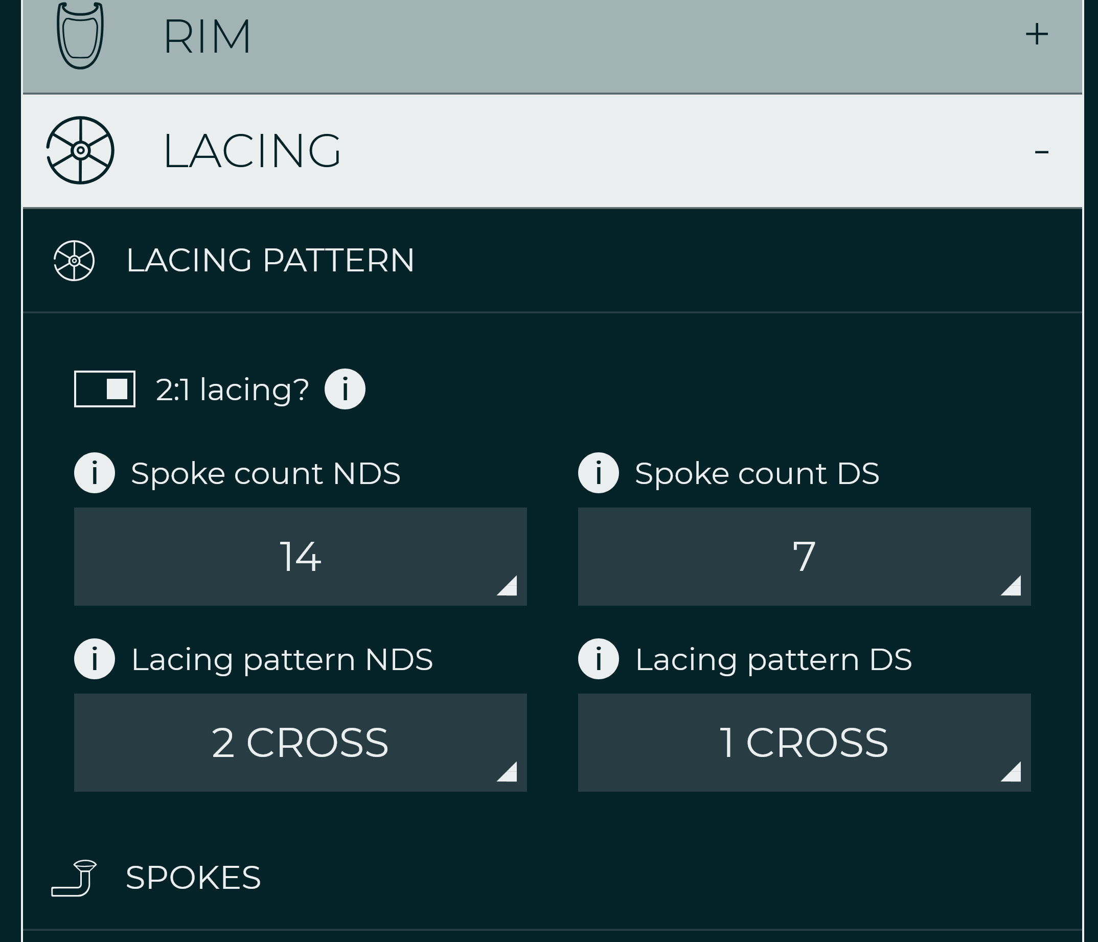
- Enable Two-To-One Lacing - To activate the two-to-one lacing pattern, simply check the "2:1 Lacing Pattern" box in the Lacing tab of the spoke calculator inside the App SpokeCalc. This will enable the correct spoke calculations for both sides of your wheel.
- Identify the Dominant Side (Auto) - In two-to-one lacing, inside the spoke calculator, the dominant side is assumed to be the one with twice as many spokes, which is the left side for front wheels and the drive side for rear wheels respectively.
- Select Spoke Count - Once the dominant side is identified, you can select the spoke count for both the dominant and non-dominant sides. The calculator will automatically adjust the lacing patterns that fit the available spoke count.
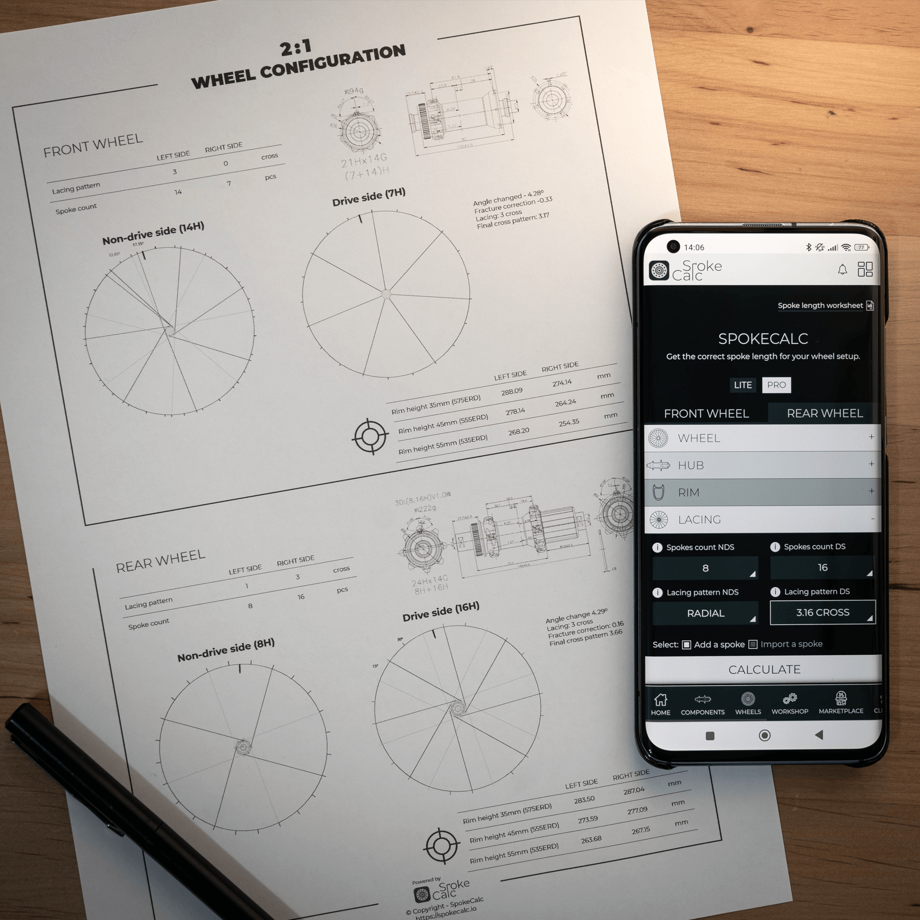
Build templates
Below are build templates for common spoke counts using the two-to-one (2:1) lacing pattern. These templates will help you select the correct spoke count and lacing pattern based on your component specifications.
I’ve structured the templates in the article by spoke count, as the same patterns can often be applied to both front and rear wheels. Freely skip the logics explained if feeling overwhelmed by it and just rely on the spoke position templates.
Note: When choosing the right template for your build—especially for straight-pull hubs—always consider the default lacing pattern of the hub itself. The spoke hole drilling on these hubs almost always dictates the lacing pattern, so ensure compatibility before proceeding.
12 by 6 (12:6) Build Template
Starting with the lowest spoke count in a two-to-one (2:1) setup, the 12:6 lacing pattern is primarily found on front disc brake wheels. Here, the dominant side (with 12 spokes) endures the braking forces, while the non-dominant side (6 spokes) primarily provides lateral support.
Due to the lower spoke count, this pattern cannot accommodate high-cross lacing. A 3-cross pattern would introduce excessive spoke angles, making it unfeasible for most hub geometries. Instead, 1-cross and 2-cross lacing patterns are common choices, depending on your hub’s flange design and diameter.
Visualizing the Lacing Pattern
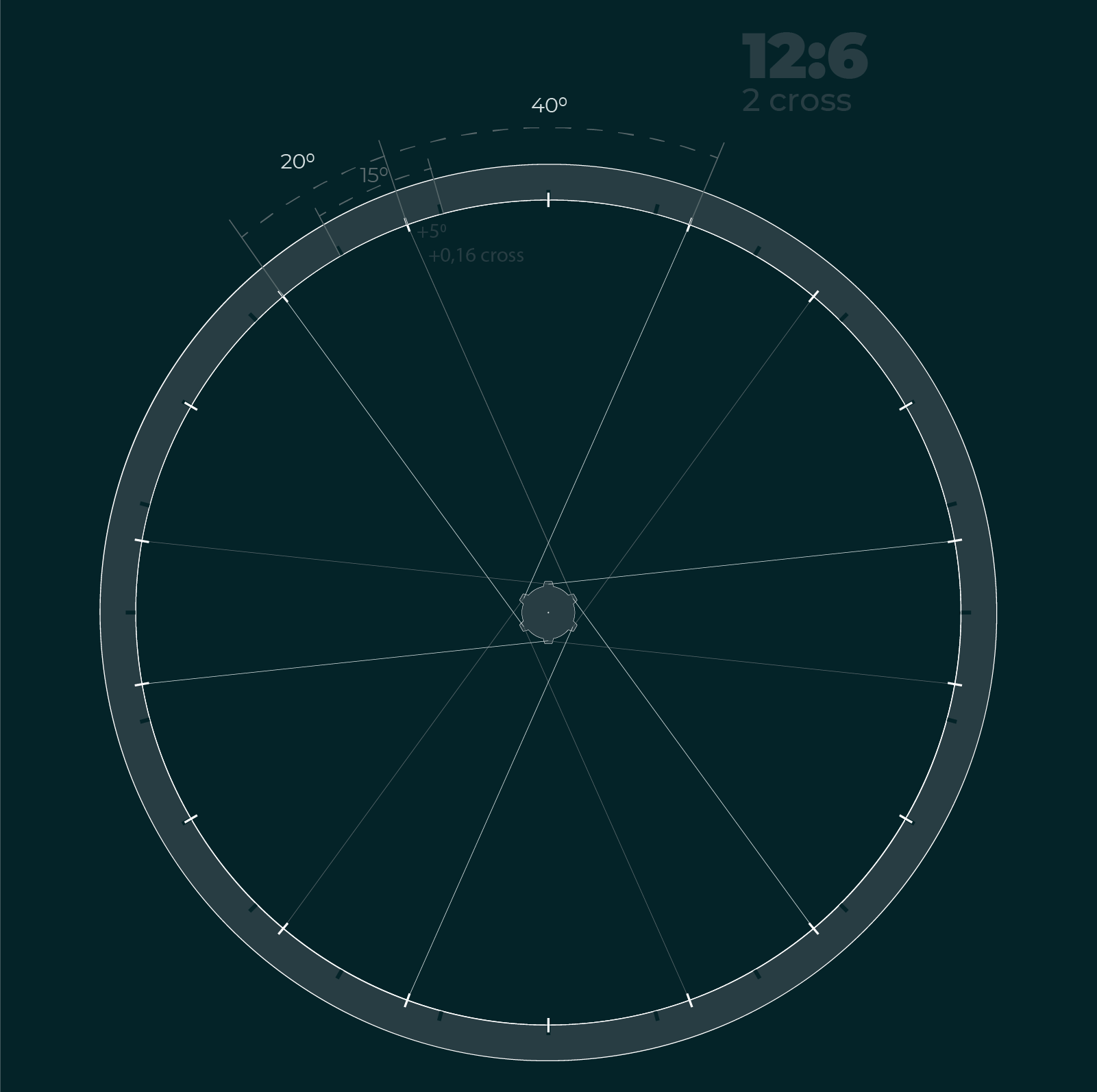
Since this is a two-to-one setup, spokes do not alternate in the conventional way. Instead, two spokes from the dominant side are followed by one from the non-dominant side. The non-dominant side is not plotted in the drawing below to maintain clarity.
The rim setup consists of 12 holes, but since the spoke holes are shared across both sides, they are arranged as if there were 18 holes, spaced 20° apart (360° / 18 = 20°).

To better understand the difference from a standard symmetrical setup, let’s compare it to a 24H rim (if both sides had 12 spokes each). In a 24H rim, holes are spaced 15° apart.
Putting it all together
Now, let’s analyze the crossing pattern shift:
- The outermost crossing spokes are 40° apart at the rim hole.
- In a standard 24H setup, the same spokes would be 30° apart (2 × 15°).
- This means the spokes in the 12:6 setup are pulled apart by an additional 10° (40° – 30°).
- Distributing this 10° across both spokes means a 5° shift per spoke, which alters the effective crossing pattern by ~0.16 cross.
Since each spoke hole represents a 0.5-cross step, this minor shift increases the lacing pattern fractionally, slightly altering spoke angle calculations.
Again, for a deeper dive, read one of my previous articles on the topic, with the focus only on 16:8 wheel case - 2:1 Two-to-one lacing pattern - Calculating spoke length for a 2:1 spoke lacing pattern.
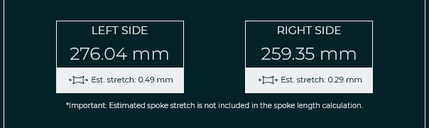
So what does that mean spoke length calculation wise? Since we are introducing a slight lacing correction factor (~0.16 cross), expect the dominant side spokes to be a bit longer compared to the standard wheel setup with double the spoke count than our dominant side (e.g., 24H in 12:6 build).
14 by 7 (14:7) Build Template
Adding two extra spokes to the dominant side, the 14:7 triplet lacing pattern provides even more lateral and torsional support than the 12:6 setup. However, in practice, this configuration is not as commonly used.
Given the relatively high spoke count on the dominant side, two viable lacing patterns are possible:
- 2-cross lacing
- 3-cross lacing
2-Cross Lacing Pattern
Following the same logic as the 12:6 case, the spoke angle shift leads to a +0.167 cross correction factor. This means that spokes will be slightly longer compared to a standard 28H symmetrical rim build.
Key takeaways for this setup:
- The spoke angle difference here is +4.3°, which is slightly lower than in the 12:6 case.
- The spacing between rim holes in a hypothetical 28H standard rim is 12.85°.
- This results in the same +0.167 cross correction factor, requiring a minor spoke length adjustment.

3-Cross Lacing Pattern
For those opting for a 3-cross pattern in a 14 by 7 builds, the same principles should apply. However, due to the additional spoke crossings, spoke angle corrections should be carefully considered to avoid extreme spoke angles at the hub flange. Expecially if a hub flange does not support such setups.
Further exploring led to the finding that when applying a 3-cross lacing pattern to a 21H triplet wheel, the situation becomes more specific and requires additional attention.
The special case
Focusing again on the two opposing spokes with the outermost crossing, our previous approach was to space them further apart compared to a hypothetical standard rim with double the spoke count of our dominant side. However, in this case, the situation changes.
Here, the dominant side spokes experience a unique angle shift, altering their exit angles at the hub flange. Due to the higher number of crossings, the spoke departure angle at the hub becomes steeper than in a lower-cross pattern, requiring a custom correction factor.
To better visualize this, look at the adjacent spoke pairs' exit angles at the hub flange. If we followed our previous approach using a 3.67-cross lacing pattern (3-cross + 0.5 straight pull correction + 0.167 two-to-one correction factor), we would exceed 100°, which is not ideal. Instead, in this case, we bring the two outermost crossing spokes closer together from the hub’s perspective.
Key takeaway: Bringing these spokes closer together, compared to a standard rim setup, introduces a negative (-0.167) lacing correction factor.
Important: Inside SpokeCalc, 14-spoke builds with 3-cross lacing patterns are automatically treated with this correction factor, ensuring that exiting spoke angles are gracefully handeled.

Note: Such type calculations with reduced spoke cross angle were performed flawlessly in the past that is why it is also proposed in this build template. For a reference, take a look at the article's last photo.
In this particular case that means the newly calculated spoke length for the dominant side will be actually shorter than on the standard 3-cross build. See the sample calculation below for a front wheel:

Straight pull vs J-bend
Even though proposed templates were made using a straight pull hub geometry with paired spokes at the hub flange, the same logic applies to classic J-bend hubs as well.
However, there is one key difference to consider:
- In straight pull hubs, spokes are paired and exit the flange in a more stretched-out manner, which increases the departure angle.
- In J-bend hubs, spokes are not as widely spaced at the hub flange, resulting in slightly smaller departure angles. Knowing that would maybe change our special case in 14 by 7 using the 3-cross on the dominant side.
Valve position
Thinking of how to position spokes in regards to the valve hole of your rim? The same logic as in standard rims apply here also and valve hole is best positioned between “parallelly positioned” trailing and leading spoke of the dominant wheel side.
Final thoughts
The two-to-one lacing pattern may be an emerging, yet powerful answer for achieving balanced tension in your wheels, but it requires careful consideration of spoke counts, lacing patterns, and component compatibility. Once familiarized with proposed build templates and calculation process, I am sure you will feel much more confident in engaging in working with such wheel setups.
Enjoyed this article?
Buy me a coffee to support my work!
Every coffee helps fuel more content like this!
About author

Aljaž Trenta
Author and founder"As a cycling enthusiast, bike mechanic and self-taught web designer, combining several of my passions and skills to build SpokeCalc was a great fun for me."